Very simple lead tester

Fing

Full time elf
Generous elf
Joined
Dec 31, 2014
Messages
405
Location
Muswellbrook
Hi everyone,
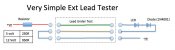
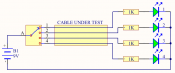
Here is a very simple 3 core extension lead tester. Basically a Yes/No tester, it won't diagnose the fault, good for a quick check if you are manufacturing a lot of leads. (this principle will also work for 2 core leads but not 4) The extra diode is there to protect the LED from reverse biasing, any basic rectifying diode will do. The resistor values are ball park figures, anything around those values should work.


Cheers
Fing


[attachimg=1]
 

Attachments

  • Lead checker.jpg
    Lead checker.jpg
    65.3 KB · Views: 181

multicast

Senior elf
Joined
Jul 13, 2013
Messages
715
ITs a good starting point.. But what happens if


(a) you've miswired some of the pins or
(b) you've got a short between some of the pins..

Do you really need the extra diode?
 

Fing

Full time elf
Generous elf
Joined
Dec 31, 2014
Messages
405
Location
Muswellbrook
hi multicast,


Valid points,
you would have to double check that the tester was correct in the first place, otherwise you'd need a tester tester…


it won't detect a short between the brown and the blue wires in the lead… but should detect all other shorts, not ideal but this is a very simple tester mainly used to check crossed connections


the extra diode could be overkill, but most LEDs have a very low reverse voltage threshold - ~4-5 volts? so this will protect the LED if the cable under test is cross wired and you are using a 12v supply
I like Fast eddy's solution to use a LAN tester, this would be a better idea if you already had a tester or the time to order one from ebay, but this simple LED trick is quick and dirty and can be made from parts lying around..( I just ordered a $5 tester from ebay to make a better version lol)
Cheers
Fing
 

David_AVD

Grandpa Elf
Community project designer
Generous elf
Joined
Jun 12, 2010
Messages
4,682
Location
Victoria Point (Brisbane)
A while ago I was thinking of making up a simple cable tester.

The basic idea is a rotary switch to select the wires (one at a time) at one of the cable with the PSU +ve.

At the other end of the cable under test, there is an LED with series resistor from each wire to the PSU -ve.

A quick rotation of the switch should illuminate each LED in turn. An LED staying off means the wire is open. An LED coming on when it shouldn't will show you what wires are shorted together.
 
Top