Adding OLED display to F16v2 BETA boards

AussiePhil

Dedicated elf
Administrator
Joined
Jun 20, 2009
Messages
1,606
Location
Canberra, ACT, Australia
When Dave redesigned the F16v2 controller as part of the beta development cycle to have an OLED display the existed beta boards then looked old hat and has been despite being arguably the most powerful controller the community has ever seen.

I asked Dave if we could retrofit the OLED display and got a "most likely" reply so I went ahead and ordered a couple of OLED displays from the same ebay seller Dave used and patiently waited for them to arrive.

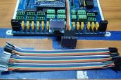
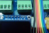
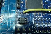
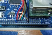
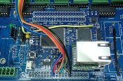
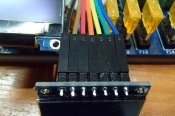
They finally arrived a couple days ago and last night I got together with Dave and he provided all the connection points needed to connect the display.
On top of that I got to test the upgrade of the board to firmware v1.0

Somewhat to Dave's pleasurable surprise I got this
P7220227.jpg


Next is to add some switches to be able to access all the additional functionality Dave has shown off.
I will do a write in posts 2 and 3 so people with beta boards can update if desired

cheers
Phil
 

AussiePhil

Dedicated elf
Administrator
Joined
Jun 20, 2009
Messages
1,606
Location
Canberra, ACT, Australia
Post 2 - Reserved for OLED install instructions.

Step 1:
Order yourself an OLED display, suggest you order this item from this seller as it have been tested
http://www.ebay.com.au/itm/400755008202?_trksid=p2057872.m2749.l2649&ssPageName=STRK%3AMEBIDX%3AIT
To ensure that this works for you it will be best just to buy the one I've linked, Dave has tried quite a few with random success.
If you have a favourite alternative seller then you must buy a 7 pin version at least.

Step 2:
Find some ribbon cable preferably colour coded to make it easier
Warm up the soldering iron and read on


This applies to FGPA board v1.0.1 .. Dave Pitt will need to confirm any variations.


The Pinouts you will need are
H1 - 40 pin header next to RJ45
GND: Pin14
VCC: Pin13
DO : Pin23
D1 : Pin21
DC : Pin19
CS : Pin24


The RES goes to Pin3 on the I2C empty header


Now some photos to help out.


I used some colour coded header wires i got in for another project but just about any ribbon cable will do
Here's the colour coding I used.
[attachimg=1]
[attachimg=5]


RES - yellow wire to Pin 3 I2C header
[attachimg=2]


The rest look like this based on the pinouts above
[attachimg=3]


And a higher level view of all the wiring
[attachimg=4]
 

Attachments

  • P8010231.jpg
    P8010231.jpg
    452.1 KB · Views: 79
  • P8010237.jpg
    P8010237.jpg
    596.3 KB · Views: 80
  • P8010245.jpg
    P8010245.jpg
    591 KB · Views: 81
  • P8010246.jpg
    P8010246.jpg
    671.8 KB · Views: 81
  • P8010232.jpg
    P8010232.jpg
    417.8 KB · Views: 81

darylc

404 darylc not found
Joined
Dec 8, 2012
Messages
1,146
Yes, I too would like to add OLED onto my beta board this weekend :)
 

AussiePhil

Dedicated elf
Administrator
Joined
Jun 20, 2009
Messages
1,606
Location
Canberra, ACT, Australia
General reply to show update in chat :)

SEE POST 2 for instructions :)


Plus add the photo of the cables used.
[attachimg=1]
 

Attachments

  • P8010235.jpg
    P8010235.jpg
    581.6 KB · Views: 82

darylc

404 darylc not found
Joined
Dec 8, 2012
Messages
1,146
Thanks Phil & Dave.

I've also added one, but I've soldered headers onto my board rather than wires to make things easier in the long term.

IMG_2741.JPG
 
Top