One of the things to consider is the "what happens if something goes wrong?"
If you have a controller that is supplying a single 5m strip on each of it's outputs and the strip only pulls 3 Amps then the controller card and fuse can handle it.
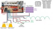
If you have many nodes which uses multiple PI points and you loose one or more of these PIs then the total load will be placed on the controller, albeit for a brief time until the controller fuse blows. The worse case would be if you lost a neg to the PI then ALL of the "return" current would go thru the controller neg connection which is not fused, most likely damaging the card.
For this reason, I only take the data from my controllers. I do not connect the controller +ve or -ve outputs. My common -ve point is seperate from the controller.
It's probably overkill, and if nothing goes wrong then it doesn't mater. But my point of view is that it doesn't add that much more to the build and it creates a more robust installation with better fault tolerance.
(as for whether the power output on cards is obsolete I'd probably agree, but i would suggest that the additional cost of providing them is minimal and it gives the card more "features"
cheers
Fing
If you have a controller that is supplying a single 5m strip on each of it's outputs and the strip only pulls 3 Amps then the controller card and fuse can handle it.
If you have many nodes which uses multiple PI points and you loose one or more of these PIs then the total load will be placed on the controller, albeit for a brief time until the controller fuse blows. The worse case would be if you lost a neg to the PI then ALL of the "return" current would go thru the controller neg connection which is not fused, most likely damaging the card.
For this reason, I only take the data from my controllers. I do not connect the controller +ve or -ve outputs. My common -ve point is seperate from the controller.
It's probably overkill, and if nothing goes wrong then it doesn't mater. But my point of view is that it doesn't add that much more to the build and it creates a more robust installation with better fault tolerance.
(as for whether the power output on cards is obsolete I'd probably agree, but i would suggest that the additional cost of providing them is minimal and it gives the card more "features"
cheers
Fing