14 gauge T or Y connectors for power injection?

XerxesDGreat

New elf
Joined
Dec 26, 2020
Messages
15
I'm putting together a buy list for my display, but am running up against a wall when it comes to the physical power injection wire and, more to the point, connections. The layout I have planned is 5V, ~6000 pixels, running off Falcon F4V3 and two receivers. Based on the power requirements, 3 power supplies seem to be okay, and I've separated up the props into 24 distinct power injection runs, ~300 pixels per run.

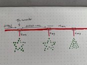
Based on this, I should be using 14awg wire, especially with some of the longer power runs (up to 70' or 20 meters). Since I'm powering multiple props off some of these runs, I'll have several branches off the main power injection line; I drew up a crude mock of what I'm talking about. Ideally, I'd like to have connections which are able to be disconnected rather than something like scotch locks, yet I haven't found any tees which would work with 14awg to keep that main line at the bigger wire size.
IMG_4855.jpg
What are you all using for this, or am I just missing something here?
 

TerryK

Retired Elf
Joined
Feb 9, 2020
Messages
655
Location
West Central Ohio
Without knowing your intended drive level it is a bit difficult to accurately comment. Working backwards from what you mentioned it would seem that you plan to drive the pixels at 50% or less. If that is 'in the ballpark' then the 14 AWG and the number of injection points and pixel per each should all work. I question the 70 foot run again due to not enough information to make a good calculation.

As to the 14 AWG Tees, most Tees (connectors too) are made to align with the 18 AWG wire which is widely used in this hobby. So I'm not sure you will be able to find 14 AWG Tees. Based on the included graphics, I might suggest 12 AWG for the first segment or 2 dropping to 14 AWG after some amperage is drawn off the bus. Be aware that having the props injected as in the graphic, sub-fusing would be recommended.
I use 14 AWG 2 conductor for power injection and as such do not use Tees. It's a bit more work but I 'Y' in to the cable using these:
 

XerxesDGreat

New elf
Joined
Dec 26, 2020
Messages
15
thanks for the comments and I can see that I missed a few key details :)

I'm planning on driving at 30% and using 3 of the falcon 8-port fused distribution blocks at 5A since the pixel wires are 22 AWG and the accepted practice is to fuse to the smallest wire; that makes 24 runs fused at 5A. Using those calculations, I estimate I can run ~300 pixels per run (0.055 * 300 * .3 = 4.95 amps) and have arranged my plans accordingly. I understand that longer runs need thicker wire due to resistance in the wire, hence edging up towards 14 AWG, but thanks for the advice on using 12 AWG for the longer run. Most of my runs will be less than 30 feet, but one is likely to end up around 70' because it's the roofline.

As for the Ys that you do, how do you use those connectors as Ys? Do you get three-port connectors and do one for positive (trunk in, branch out, trunk out) and one for negative? Or am I just missing the point and it's actually common practice to do one power injection cable to each prop?
 

TerryK

Retired Elf
Joined
Feb 9, 2020
Messages
655
Location
West Central Ohio
...
As for the Ys that you do, how do you use those connectors as Ys? Do you get three-port connectors and do one for positive (trunk in, branch out, trunk out) and one for negative? Or am I just missing the point and it's actually common practice to do one power injection cable to each prop?
The connectors I use are 2 pin. The cable wires on the out end, the 3 each V+s and 3 V-s [GND}) are soldered and heat-shrinked. Current practice is male on the in end and a pair of females on the out, one female connector to the prop and the other female connector to a following cable going downstream to the next prop. In essence a number of various length cables which will help with future location changes. So far I've only 12 Volt pixels so I do not need to be concerned about voltage mixups. From the controller no power, data only which is presently via 24 AWG shielded 2 conductor (Belden). Data line connectors are:

There is no common practice I think, pretty much what works for your display. I have a Boscoyo train and each car has its own feed. Also have a pair of GE snowflakes which both are on a single cable from the supply. Because of how I implemented power injection I sub-fuse, would be a hazard if I did not.
 

XerxesDGreat

New elf
Joined
Dec 26, 2020
Messages
15
Ah, I think I understand; you're building your own Ys by soldering more than one cable together, then using the automotive connectors to provide quick disconnects in each direction. That's clever; never even thought of doing that. Thanks for the help!
 

i13

Dedicated elf
Joined
Jul 5, 2013
Messages
1,172
Be careful when using the brightness and therefore the data to limit the current draw. If the data signal gets corrupted then the pixels could turn on at whatever jumbled brightness they happen to get from the corrupt data.

14 AWG might be cutting it close. Although it can safely handle the current (assuming that it doesn't increase due to my above point), the resistance in this wire might still be enough to cause incorrect colours due to voltage drop. It is possible to calculate a voltage drop if you know how many pixels are branched off of the wire and at what distances. Regardless of the amount of voltage drop that occurs, I can think of three ways to reduce it:
I have used a different technique to branch off of thicker (8 AWG from memory) power cables. I used two separate single cables (not figure-8 cable), cut into the side of the insulation to expose the wire and branched smaller wires off of it. I was able to seal it up with heatshrink and silicone or liquid electrical tape. The thicker wire is a continuous run without connectors breaking it up.
 

TerryK

Retired Elf
Joined
Feb 9, 2020
Messages
655
Location
West Central Ohio
Ah, I think I understand; you're building your own Ys by soldering more than one cable together, then using the automotive connectors to provide quick disconnects in each direction. That's clever; never even thought of doing that. Thanks for the help!
Precisely. My prop locations are not definite so this method gives me flexibility. If all goes as planned, I should have a few props out about 200 feet December 2021. It will be interesting (and could prove to be an exercise in futility).
 

XerxesDGreat

New elf
Joined
Dec 26, 2020
Messages
15
i13, thanks for the additional ideas! I've been playing around with how to minimize the straight runs of power injection cable and the longest two I have now is just over 15m/50ft, each with around 300 pixels; I've switched my plans to use 12AWG for those all the way down. Due to what these particular runs look like (roof outline), I'm planning on just running the 12AWG parallel to the signal and connect the two every 100 pixels. And yes, I'm strongly considering going to 12V for the outlines for exactly this reason :)
 

BRW

New Elf
Joined
Nov 12, 2020
Messages
36
Location
Austin, TX USA
  • Use a higher voltage (e.g. 12V, 24V, 31V because it doesn't matter too much) and use a DC-DC convertor each time you branch off of it.
Thanks for this. I've been looking at 12V because I plan on using server psus for several reasons, But the props (5' trees mainly) seem to lend themselves to 5V use. Distributing 12V and converting to 5V seems to be a functional plan for my 1st display.

Keep sharing the good stuff!
 

i13

Dedicated elf
Joined
Jul 5, 2013
Messages
1,172
I do have some DC-DC convertors in my display. My display is mostly 31V traditional LED strings and it is handy to have DC-DC convertors for when I want to have a small 5V or 12V item that's on its own and not near a 5V or 12V power supply. I've never had a problem with the convertors but I'd recommend being careful to avoid overloading them. I've noticed that their voltage output increases by around 0.05V when I put them under load. This is obviously not a problem but darylc had one output 7V and it fried some of his 5V P10 panels.
 

TerryK

Retired Elf
Joined
Feb 9, 2020
Messages
655
Location
West Central Ohio
Thanks for this. I've been looking at 12V because I plan on using server psus for several reasons, But the props (5' trees mainly) seem to lend themselves to 5V use. Distributing 12V and converting to 5V seems to be a functional plan for my 1st display.

Keep sharing the good stuff!
If you have a fair number of 5 Volt pixels it may be a better option to use a typical AC to DC supply rather than trying to step down DC to DC. The use of a DC to DC converter adds complexity and as they are active power supply devices should (or need to) be properly implemented as would any other power supply; proper wire sizing and fusing as such. DC to DC converters can be had built to various types, qualities (one gets what one pays for), and efficiency's. They tend to operate best when the Vout is near the Vin and current demand is in their mid to upper capability range. Manufacture spec sheets for the better quality converters substantiate this.

Your post insinuates that you have not yet purchased 5 Volt pixels. If that is the case then I suggest following the recommendation that it is better to avoid having mixed voltage displays.
 

i13

Dedicated elf
Joined
Jul 5, 2013
Messages
1,172
I only use DC-DC convertors when I have a small number of pixels that are a long distance from the nearest power supply that outputs their voltage. DC-DC convertors work fine for me but if I used them excessively, it would reach a point where it would be cheaper to just have more power supplies.

My display is a combination of 5V, 12V and 31V. The 31V only powers the traditional LED strings and a few DC-DC convertors. I think it is worth considering having a mixed voltage pixel display. IMO, different voltages suit different display items. As a general rule, I think 5V is a sensible choice when there are a large number of pixels in a small area. 12V is a sensible choice when there are a small number of spread over a large area. Your display might be a combination of both.

Explaining my viewpoint further, I usually don't want to make a compromise in the design of one display item because unrelated items exist somewhere else in the display. In an established display, there would hopefully be enough power supplies that you could separately choose a voltage for each new small display item and it is likely that there would be a compatible power supply nearby. A DC-DC convertor can help when there isn't. Large display items will need their own power supplies so they're independent from everything else. Having so much 31V means that I can drop down to 12V with a DC-DC convertor. Although most pixel displays won't have the 31V power supplies to facilitate dropping down to 12V, 12V display items can be placed further from their 12V power supplies than 5V before voltage drop causes problems. 12V display items also max out the power supplies with fewer pixels than 5V so more 12V supplies are required, meaning they can be closer to the display items. I power all of my pixels with injection and not through the controller. This means that I can have the controller powered with one voltage and the pixels with another voltage. I can also run 5V and 12V pixels end-to-end with their own power supplies.

I do see some arguments against mixed voltage displays but I don't think they're strong enough to mean that you shouldn't consider doing it. Firstly, my viewpoint might not apply if you choose to distribute all of your power from one central place. Secondly, you need to be careful not to accidentally power things at the wrong voltage. Thirdly, it depends on the design of the display. If the same voltage happens to be the most suitable for all items in your display then you'd use one voltage. Fourthly, if you're adding a small display item with pixel nodes and there are 12V supplies nearby, using 12V instead of 5V will waste power (the advantage of 5V nodes) but it won't waste too much because a small display item won't have a large number of pixels.
 
Top