Advice please on my setup and xLights Question

wce06

Apprentice elf
Joined
Nov 22, 2016
Messages
68
Location
Bendigo
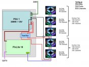
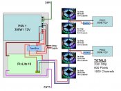
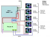
In the attached picture I have added my configuration, could I please get some feedback on errors or room to improve?


Also in the totals you will see that I have 1800 channels planned for this setup, do I simply run a single data wire to the section I need to start a new output???? The reason I ask is that each of my PixLite 16 outputs is only 512 channels (I think I have that correct).


So like power injection how do I add the new data outputs, or do I simply have to break up my plan into 512 channel lots?


I hope all that made a small amount of sense..


wce06
 

Attachments

  • Setup.jpg
    Setup.jpg
    76.4 KB · Views: 95

wce06

Apprentice elf
Joined
Nov 22, 2016
Messages
68
Location
Bendigo
but how long can I run my power cable before it losses voltage or does it only start loosing once it hits the lights?


These power supplies will be used for other lights aswell. They will be spread out, and the lights I am using in the attached design are along my roof edge so covers about 20m.
 

wce06

Apprentice elf
Joined
Nov 22, 2016
Messages
68
Location
Bendigo
Thanks for the help, just a little confused....on the whole channels thing
 

danv

Full time elf
Joined
Dec 5, 2016
Messages
220
Location
Rockhampton
What size (in mm2) is the power cable you are using? is it figure 8 cable? multi-stranded?


Voltage Drop is dependent on current flowing through the conductor and conductor resistance (ohms law Voltage = Current x Resistance)


If you could provide some further information I would be happy to do some calcs for you?
 

wce06

Apprentice elf
Joined
Nov 22, 2016
Messages
68
Location
Bendigo
Where do I split my display to add the second output, in order to split the 1800 channels
 

Fing

Full time elf
Generous elf
Joined
Dec 31, 2014
Messages
405
Location
Muswellbrook
hi
the pixlite 16 can only do 340 pixels per output. so you will need two outputs to do this. The Pixlite 4 can do 680 pixels.
Personally I don't run any power ( this includes the Negative) thru my controllers. It also helps to stop earth loop issues.


Work on the assumption that each pixel will use 60mA (0.06A) for full white. multiply by the number of pixels to get your total current demand. then work out how many power supplies you need. I am supplying a 18m run of strip with just two injections, one at the start and one at 10m. I use 1.5mm2 cable. I only use one power supply but it is a meanwell and rated at 100% duty.


from memory a 10/30 strip uses 3A per 5m? so 20m will need 12A, which at 12v is 144W, so well within the ability of one 340w PSU.


Cheers
Fing
 

Fing

Full time elf
Generous elf
Joined
Dec 31, 2014
Messages
405
Location
Muswellbrook
Part 2.
referring to your diagram. and not taking into consideration any other lights..


1. remove the black wire from the pix16 to the first strip.
2. replace it with a black wire from the start of the first strip to the neg on PSU1.
3. Remove the red wire from the output of the pix16 to the fusebox and connect it to the PSU1 +ve
3. remove PSU2 and PSU3.
4. break the strip where PSU2 used to connect.this will give you 2 strings of 300 pixels
5. connect the +ve of the 2nd string to the fusebox and the neg to the PSU1.
6. connect the data of the 2nd string to another output of the pix16.


now this should work on paper, but (there's always a but) you may need to add power injection..... also this doesn't take into account the physical shape of your strips and where the controller is located. it may be easy to say use 3 outputs instead etc...


hope this helps
Cheers
Fing
 

wce06

Apprentice elf
Joined
Nov 22, 2016
Messages
68
Location
Bendigo
Ok so thanks to Fing's advice, I have re-drawn my diagram, any further advice is much appreciated. I have also included a diagram of where the lights will be going on my house.


I am a little worried about the length of cable I will need to reach Section Two from the PSU, I may have to add a PSU, but I will test the voltage drop when I have it in place.


I think once I get this very first roof line done I should be good to start tackling some other projects throughout the year ready for 2017 Christmas.


CAT5 label is meant to be to the left with the purple wire...ooops
 

Attachments

  • Wiring Part1.JPG
    Wiring Part1.JPG
    73.4 KB · Views: 64
  • House Part2.JPG
    House Part2.JPG
    103.8 KB · Views: 55

i13

Dedicated elf
Joined
Jul 5, 2013
Messages
1,172
I'm thinking that your pixel counts might be wrong. If this is the 12V strip with 30 LEDs per metre then you should only have 10 pixels per metre because each pixel has three RGB LEDs. If these are WS2811 pixels then they can't draw more than 55.5 mA per pixel. Your diagram should only have a total of 200 pixels.

You have lengths that add up to 10 metres without power injection and this means you'll get voltage drop.

I think that what you had in your post at the start of this thread was better. The power injection was correct. If there are going to be extra power supplies in those locations anyway then you may as well use them.
 

wce06

Apprentice elf
Joined
Nov 22, 2016
Messages
68
Location
Bendigo
Thanks I13, I guess everyone has different ways of doing things. A little confused which way I should go now, may just trial both way and see how I go, I have 12 months to sort it out.


Just another quick question, Ray Wu sent me the WS2811 strip lights and they already have a power injection cable soldered into it, if I am using the one power supply can I loop positive and negative wires?
 

Fing

Full time elf
Generous elf
Joined
Dec 31, 2014
Messages
405
Location
Muswellbrook
hi,
Damn I missed that, I13 is correct your pixel count is wrong. the standard 30/10 strip will give you 10 pixel nodes per metre, so a total of 200 nodes (pixels)


therefore a pix16 is able to supply them all from one output.


your latest diagram is "correct" and a good way to implement your wiring. No negative loops and no power running thru the pixlite


but(there's always a but) with only 200 nodes you can further "adjust" the diagram by using only one output and just string the data and power thru them all. then add power injection by coming from the fusebox to a convenient point(s).


by using only one PSU you won't have any Power injection Dramas.


Looking quickly at your house my first guess would be to inject at 6m and 17m as they seem to be the shortest run from PSU1, remember when you power inject the voltage goes both ways..


another way of "power injecting" is to provide a big cable that runs alongside the strip. the strip only has a small section of copper which is where the problems come from. By putting a larger cable in parallel with the strip it may reduce your voltage drop problems.


I have 6 arches across my front yard. each arch has 2.5m of strip, so all up 15m. the arches are constructed on a base of electrical conduit which enables them to be free standing. I have a pigtail connector at each end and there is a 2.5mm2 +ve and -neg cable that runs thru the base that connects the start and end of the strip together.


the arches are daisy chained together, and feed at one end only by a 1.5mm2 cable from a pixlite16 11m away. I have no problems with voltage drop.


this is a form of looping. (does this make sense?)


Cheers
Fing
 

wce06

Apprentice elf
Joined
Nov 22, 2016
Messages
68
Location
Bendigo
Cool, thanks i13 and Fing


I think I will go with the attached method, I will have the luxury of having other power supplies within the area so will be able to inject power if required (if using a second PSU I will ensure the GND is connected between all the PSU's and the +ve is not connected between PSU's).


Thanks again hopefully the attached diagram is good to go....lol


i13 - just to confirm on my strip there are three 50/50 RGB LED in a section (30 50/50 RGB LED per meter) and these are counted as one pixel (three channels). Which totals 50 pixels / 150 channels per roll (5m). Just when I thought I understood it all.... :( 
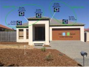
I thought each 50/50 RGB LED counted as three channels and I counted each one on a roll and there was 30 per meter? ??? ??
 

Attachments

  • Wiring Part1 ed3.jpg
    Wiring Part1 ed3.jpg
    70.7 KB · Views: 43
Top