
Hi All first attempt at power injection and really worried I am going to burn the house down (well husband is anyway). Have read and watched a lot of videos and forums about this and think I am on the right track but would like to be sure please. The way I have my display it is easier and tidier to have a separate power supply mounted next to my Advatek box undercover and out of the elements. It will plug straight back into a power point using a lead with power point plug at the end from an old computer cord I had. Now the only thing I am worried about (you might find more problems) is how does the ground power get out and also what size fuse should I be running. I was going to inject in the middle but it will sit neater and more flush from the end. I have soldered the string of 158 already and cut the v+ wire at node 79. The hat has a matrix I am going to run on a separate output and will need to inject that as well as it is 168 pixels so will use the same set up into the same power supply if I am on the right track. I have a 6 space fuse block. I wont use the boscoyo template in xlights as I am separating it and will run the outline of 158 as a circle image for sequencing and the matrix section as a stand alone matrix panel. Hope you can help thankyou.
You are using an out of date browser. It may not display this or other websites correctly.
You should upgrade or use an alternative browser.
You should upgrade or use an alternative browser.
Am I on the right track-update Part 2 more problems
- Thread starter Julie
- Start date
It would help if you could draw a diagram of this. I'm not sure whether I understand your "how does the ground power get out" question. The negative should be injected alongside the positive. The current needs to flow through both in order to complete the circuit so there's no need to fuse the negative.
Assuming that you're using WS2811 or equivalent pixels at 100% brightness, they won't exceed 55.5 mA per pixel. Multiplying this by the number of pixels will give you a sensible fuse size. Measuring their actual current draw would be even better. If you run the pixels at a lower brightness, I suggest fusing for the brightness that you have designed for. For example, if your power supply and cable are capable of running the pixels at 80% brightness but you itend to run them at 50% brightness, you may as well fuse them for 80% brightness because accidentally running them at 80% brightness won't damage anything.
I definitely agree that it is worth using power injection because it allows more flexibility in the setup and more pixels per controller. I have used it to run 5V and 12V pixels end-to-end on the same controller output.
- Thread starter
- #3
Sorry thought I had uploaded the image but it was too big Lets try this again. My husband says my drawing that the ground power coming in both directions it cant get out.It would help if you could draw a diagram of this. I'm not sure whether I understand your "how does the ground power get out" question. The negative should be injected alongside the positive. The current needs to flow through both in order to complete the circuit so there's no need to fuse the negative.
Assuming that you're using WS2811 or equivalent pixels at 100% brightness, they won't exceed 55.5 mA per pixel. Multiplying this by the number of pixels will give you a sensible fuse size. Measuring their actual current draw would be even better. If you run the pixels at a lower brightness, I suggest fusing for the brightness that you have designed for. For example, if your power supply and cable are capable of running the pixels at 80% brightness but you itend to run them at 50% brightness, you may as well fuse them for 80% brightness because accidentally running them at 80% brightness won't damage anything.
I definitely agree that it is worth using power injection because it allows more flexibility in the setup and more pixels per controller. I have used it to run 5V and 12V pixels end-to-end on the same controller output.
Attachments
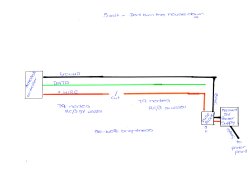
The injection in the drawing looks correct. The only thing that might happen is some incorrect colours near the cut because 79 nodes powered at one end is quite a lot for 5V. At 50-60% brightness it is worth a try.
I'm not sure what your husband means about the power not being able to get out. The current completes the circuit by flowing through the pixels themselves. If the current couldn't "get out" then no current would flow and nothing would happen at all.
I'm not sure what your husband means about the power not being able to get out. The current completes the circuit by flowing through the pixels themselves. If the current couldn't "get out" then no current would flow and nothing would happen at all.
Notenoughlights
400,000+ twinkly lights
Assuming you have a power feed to run the controller, looks good to me.
- Thread starter
- #6
Thankyou yes I was not understanding what he meant but thought I would ask. I don’t know how I manage it but I have 99 5volt pixels on a string without injection at 50% and no pink in the white it starts to appear at 70% very odd but I am not complaining. Will do the calculation to sort the fuse size. Thankyou so muchThe injection in the drawing looks correct. The only thing that might happen is some incorrect colours near the cut because 79 nodes powered at one end is quite a lot for 5V. At 50-60% brightness it is worth a try.
I'm not sure what your husband means about the power not being able to get out. The current completes the circuit by flowing through the pixels themselves. If the current couldn't "get out" then no current would flow and nothing would happen at all.
- Thread starter
- #7
Update on my first attempt. Did not go to plan sadly. The first section of string straight from the Advatek Controller of 80 lights 5volt at 50% have all come up beautifully and the white is just starting to pink on the last few pixels. Now as per the sketch attached things go weird. The First 19 lights after the cut furthest away from the injection powered come on fine however the rest of the string nothing. Thoughts please.
Either you don't have enough pixels configured or there's a faulty pixel. If you have another string of pixels that you can easily swap out in order to check the configuration, give this a try. Another option is to put this string of pixels on a different controller. If you don't already have one, I suggest getting a tester. They're available from several lighting suppliers and Ebay: https://www.aliexpress.com/item/32261108366.html
If you're sure that everything is configured correctly, cut out and replace the last working pixel and the first non-working pixel. The reason for replacing the last working pixel is because it might not be passing the data on to the rest of the pixels.
If you're sure that everything is configured correctly, cut out and replace the last working pixel and the first non-working pixel. The reason for replacing the last working pixel is because it might not be passing the data on to the rest of the pixels.
abundy
Full time elf
Julie, there are also local suppliers who also have this same pixel tester, such as Al Hanson -
 www.hansonelectronics.com.au
Support Local when you can.
www.hansonelectronics.com.au
www.hansonelectronics.com.au
Support Local when you can.
Pixel tester 2811 | Hanson Electronics
Simple WS2811 pixel tester/controller
www.hansonelectronics.com.au
Hanson Electronics
Hanson Electronics Christmas Light Controllers Custom electronics
www.hansonelectronics.com.au