freaky but frustrating

nzlongfellow

Dennis from NZ
Joined
Jan 2, 2014
Messages
538
Location
Lepperton, Taranaki
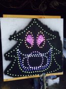
In the final stages of finishing my singing faces and connected up a 27 Channel controller.
When I applied power all the pixels lit up.
There are 8 circuits with Dumb RGB's so 24 outputs used. Running 5V supply.


(Ah i think somewhere 5V is too low to run these boards)... I digress.


THE Freaky part is that when I looked at the lights they were all at the correct colour...NO controller and all DIP switches off.
 

Attachments

  • FullSizeRender.jpg
    FullSizeRender.jpg
    303.4 KB · Views: 65

AAH

I love blinky lights :)
Community project designer
Joined
Dec 27, 2010
Messages
4,190
Location
Eaglehawk
You can run the board off 5V if you mod it alternately you can run the board off 12V for instance but have the outputs switching 5V by connecting all the +ve's to a 5V supply with the -ve of said supply hooked up to 27ch board.
 

nzlongfellow

Dennis from NZ
Joined
Jan 2, 2014
Messages
538
Location
Lepperton, Taranaki
Alan, I don't have the Ray Wu 27 Channels.
Can you please indicate if I have selected the right areas on my boards to convert to 5V.
Here are the pics of mine.
 

Attachments

  • 27channel.zip
    6.9 MB · Views: 7
  • Remove D2.png
    Remove D2.png
    477.5 KB · Views: 19
  • Zener and Fuse.png
    Zener and Fuse.png
    625.9 KB · Views: 17

AAH

I love blinky lights :)
Community project designer
Joined
Dec 27, 2010
Messages
4,190
Location
Eaglehawk
That looks about right but a bit hard to tell without 1 in front of me. The zener is there to provide some protection for the board if you happen to put too high a voltage onto it or you reverse the connections. There's probably no need to remove D2 as it gets bridged out of the circuit by the link/fuse. The fuse probably only needs to be 1/2A rated or thereabouts. It is only powering the pcb logic and ideally should be sized so that it blows before the zener is vaporised if you do something wrong.
 

nzlongfellow

Dennis from NZ
Joined
Jan 2, 2014
Messages
538
Location
Lepperton, Taranaki
AAH said:
That looks about right but a bit hard to tell without 1 in front of me. The zener is there to provide some protection for the board if you happen to put too high a voltage onto it or you reverse the connections. There's probably no need to remove D2 as it gets bridged out of the circuit by the link/fuse. The fuse probably only needs to be 1/2A rated or thereabouts. It is only powering the pcb logic and ideally should be sized so that it blows before the zener is vaporised if you do something wrong.
Thanks Alan, I tried one and it works so ordered the rest of the parts to convert them all.
And D2 does not have to be removed.
 
Top