
GCAllan
New elf
Hello All
Firstly thankyou all very much for this wonderful forum housed with years of experience. It has consumed many hours of my time reading and learning and going "HUH" how does that work!!
Anyway, always been a keen enthusiast of XMAS lights but this year decided to make them computerised. I've spent most of my working life in the IT networking space. The fact that i'm going to put some of the Cisco kit I've hoarded over the years around my front yard to make lights flash amuses me somewhat. Don't think that's what Cisco intended.
So after the research I have done on this forum, I decided to buy a Pixlite 16 and use Vixen 3, with a myriad of pixel nodes and strips from Ray WU, all 2811. I've had a play and things flash and blink and much to my "minister of war and finance's" displeasure, I don't WANT, I NEED more.
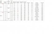
So to the nitty gritty, I have made myself a spreadsheet and wiring diagram of the pixels I want to hang off the Pixlite and power wise I think it's overloaded. So before I make things potentially SMOKE I thought I would get validation from you guys i'm on the right track. The total Amps is over the recommended 32A per bank and 3 of the Pixlite outputs end up more than the recommended 7.5A.
I believe this would only occur if all lights are on at once at maximum intensity on white?
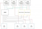
After reading the bible and power injections forums, I believe I can overcome these issues by using 4 x 350W power supplies and using 2, 1 on each bank powering a subset of the lights and 2 more to power the other subset of lights independent of the Pixlite. All GND's are connected by a GND Bus Bar.
I am also unsure that the GND connection to the second subset of lights should be off the GND Bus Bar or off the Pixlite GND connections or does it not matter!!!
Anyway hoping someone will guide me in the right direction and certainly looking forward to the rest of the year building up my display and hoping it all works on go-live.
Thanks again for the wealth of information available on this forum.
Thanks
Al
Firstly thankyou all very much for this wonderful forum housed with years of experience. It has consumed many hours of my time reading and learning and going "HUH" how does that work!!
Anyway, always been a keen enthusiast of XMAS lights but this year decided to make them computerised. I've spent most of my working life in the IT networking space. The fact that i'm going to put some of the Cisco kit I've hoarded over the years around my front yard to make lights flash amuses me somewhat. Don't think that's what Cisco intended.
So after the research I have done on this forum, I decided to buy a Pixlite 16 and use Vixen 3, with a myriad of pixel nodes and strips from Ray WU, all 2811. I've had a play and things flash and blink and much to my "minister of war and finance's" displeasure, I don't WANT, I NEED more.
So to the nitty gritty, I have made myself a spreadsheet and wiring diagram of the pixels I want to hang off the Pixlite and power wise I think it's overloaded. So before I make things potentially SMOKE I thought I would get validation from you guys i'm on the right track. The total Amps is over the recommended 32A per bank and 3 of the Pixlite outputs end up more than the recommended 7.5A.
I believe this would only occur if all lights are on at once at maximum intensity on white?
After reading the bible and power injections forums, I believe I can overcome these issues by using 4 x 350W power supplies and using 2, 1 on each bank powering a subset of the lights and 2 more to power the other subset of lights independent of the Pixlite. All GND's are connected by a GND Bus Bar.
I am also unsure that the GND connection to the second subset of lights should be off the GND Bus Bar or off the Pixlite GND connections or does it not matter!!!
Anyway hoping someone will guide me in the right direction and certainly looking forward to the rest of the year building up my display and hoping it all works on go-live.
Thanks again for the wealth of information available on this forum.
Thanks
Al

")
