
You are using an out of date browser. It may not display this or other websites correctly.
You should upgrade or use an alternative browser.
You should upgrade or use an alternative browser.
IR Flood lights to wired
- Thread starter assilem4791
- Start date
assilem4791
If I rest, I rust.
- Thread starter
- #2
I was thinking perhaps I could just run a data wire & ground from the controller since this has it's own power (I hope that makes sense).
TerryK
Retired Elf
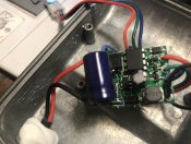
I cannot determine precisely but it'll be a bit more involved I'm afraid. From the photos best as I can determine the RGB LEDs are transistor driven via the 8 pin IC. As it appears that the input command sensor goes to that IC, I suspect that IC is a PIC of some sorts. That IC will then be the determining factor on what needs done to drive the LEDs from a RGB pixel controller. Is there a number on the 8 pin IC? Numbers on the transistors, the 3 pin devices located close to the RGB/Black wires routed to the LEDs would be nice too although not necessary.
A little good news, these do look like they could be converted I think. My thought is once the IC is known it may be possible to repurpose. If not, remove it and patch in a WS2811 or similar IC.
A little good news, these do look like they could be converted I think. My thought is once the IC is known it may be possible to repurpose. If not, remove it and patch in a WS2811 or similar IC.
burnt
Full time elf
- Joined
- Nov 17, 2014
- Messages
- 189
i would use a controller like this
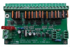 just place the 3 leads in to the output of this controller. it will work as 2811 pixel, http://www.hansonelectronics.com.au/product/2811dc15/
assilem4791
If I rest, I rust.
- Thread starter
- #5
On the one I opened the numbers were scrubbed. I can try one of the others. Maybe someone missed scrubbing the IC in one of the others.I cannot determine precisely but it'll be a bit more involved I'm afraid. From the photos best as I can determine the RGB LEDs are transistor driven via the 8 pin IC. As it appears that the input command sensor goes to that IC, I suspect that IC is a PIC of some sorts. That IC will then be the determining factor on what needs done to drive the LEDs from a RGB pixel controller. Is there a number on the 8 pin IC? Numbers on the transistors, the 3 pin devices located close to the RGB/Black wires routed to the LEDs would be nice too although not necessary.
A little good news, these do look like they could be converted I think. My thought is once the IC is known it may be possible to repurpose. If not, remove it and patch in a WS2811 or similar IC.
Katekate
Senior elf
you will have to trash that circuit that is in there and build something else.
You could run out the wires to the led into the hanson board linked above, or swap in some kind of WS2811 board. or you can trash the whole insides and put in something like this https://www.aliexpress.com/item/4001076924352.html
You could run out the wires to the led into the hanson board linked above, or swap in some kind of WS2811 board. or you can trash the whole insides and put in something like this https://www.aliexpress.com/item/4001076924352.html
assilem4791
If I rest, I rust.
- Thread starter
- #7

assilem4791
If I rest, I rust.
- Thread starter
- #8
Above is our normal display. I want to replace the spotlights with the RGB spotlights.
TerryK
Retired Elf
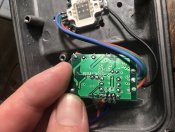
In the second photo, is the legend under the blue wire V- or V+?
Katekate
Senior elf
its def V+, because the colours are labeled R- G- B-
pretty much everything is common anode these days.
pretty much everything is common anode these days.
assilem4791
If I rest, I rust.
- Thread starter
- #11
V+In the second photo, is the legend under the blue wire V- or V+?
TerryK
Retired Elf
I suspected it was V+, just verifying.
As I see it the choices are...
1. The Hanson device or similar (Light-O-Rama?); probably the easiest method and least economical.
2. AliExpress device Kate mentioned; essentially keep the housing and replace the electronics.
3. Patch in a WS2811; most complex and economical. Bare WS2811s are a bit scare although a vendor I frequent stocks them.
assilem4791
If I rest, I rust.
- Thread starter
- #13
Yerp, just opened another one and it too is scrubbed. Turds. Guess I'll be gutting them.
if your going to gut them (do what i did to my blown 50w leds floods) https://www.tindie.com/products/robg/pixelflood-20w-rgb-flood-light-ws2811-pixel/
great piece of diy kit
great piece of diy kit
assilem4791
If I rest, I rust.
- Thread starter
- #15
Thanks!! What controller do you use, as these are 24v?if your going to gut them (do what i did to my blown 50w leds floods) https://www.tindie.com/products/robg/pixelflood-20w-rgb-flood-light-ws2811-pixel/
great piece of diy kit