Power injection and common GND

Madko

Full time elf
Joined
Dec 24, 2012
Messages
250
Location
Castle Hill NSW
Hey Guys,


I'm running P12S and P12R. Each controller, I have connected 2 x 12v power supplies. One power supply for P00,one half the controller and the other power supply feeding P13 for the other half. My wiring is following option 3 of the ECG-P12R PDF.


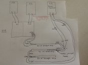
When using power injection from a separate 12v power supply, which isn't connected in anyway to the controller, Is it correct in saying that the Data line flows from controller output through say 3 x 5m, 30LED/m strip and at the beginning of the 2nd and 3rd strip (forgetting the first strip as this is power feed from the controller output itself) and connecting the +12v and the GND to the corresponding copper pads on the strips? Is there a need to connect DC Output GND of the power supply, which is used for power injecting to any other GND of another power supply? Or is connecting GND's together via the strip all that needs to be done to make it equal potential?
I have attached a drawing image that has the way I'm thinking of joining the GND's through the strip. Is the red link wire required?


Hope that makes some sort of sense


Thanks
 

Attachments

  • image.jpg
    image.jpg
    201.1 KB · Views: 112

fasteddy

I have C.L.A.P
Global moderator
Joined
Apr 26, 2010
Messages
6,648
Location
Albion Park NSW
The ground needs to be tied at the strip/string. It is not needed to connect the power supplies directly together because in most cases the 2 power supplies are far apart anyway.
 

BundyRoy

Dedicated elf
Joined
Apr 9, 2014
Messages
1,026
I know the drawing is only a sketch but another point is if it means less cable the bottom strip could be powered from the right hand end (as drawn on the page). The power can be connected to either end.
 

marmalade

cats & pixels
Joined
Dec 1, 2015
Messages
284
Location
newcastle
Remember try not to parallel the outputs of multiple switch mode power supplies together unless you are certain the smps are designed to do so. Even meanwell advises against it unless using their current sharing versions.

Also watch for ground loops as this can cause weird things such as noise getting into the data lines.
 

Madko

Full time elf
Joined
Dec 24, 2012
Messages
250
Location
Castle Hill NSW
Thanks guys for making it a lot clearer! Cheers


marmalade said:
Remember try not to parallel the outputs of multiple switch mode power supplies together unless you are certain the smps are designed to do so. Even meanwell advises against it unless using their current sharing versions.

Also watch for ground loops as this can cause weird things such as noise getting into the data lines.


Can you please explain this in further detail? Are you referring to my drawing on the power inject SMPS were I have 2 GND feeds coming from the output side feeding my strips? If so, how would I achieve this without creating GND loops?
 

Fing

Full time elf
Generous elf
Joined
Dec 31, 2014
Messages
405
Location
Muswellbrook
Hi,
don't connect the two power supply -ve together at the supplies you've marked in red. This will create a Loop and*may* cause you problems as marmalade said.


I have a similar set up but I only had to inject at the 10m point, so power at the start and inject at the strip2-3 join. you may be able to get away with only injecting at the start and end, but there are a lot of variables to take into consideration.


also depending on your load and the power supply capacity the second power supply may not be necessary, just connect the power injection to the first power supply . In my setup the controller does not supply the +ve and -ve because the current is more than the controller can handle, I just take the data from the controller and the power directly from the power supply (via fuses)


Cheers
Fing
 

Madko

Full time elf
Joined
Dec 24, 2012
Messages
250
Location
Castle Hill NSW
Fing said:
Hi,
don't connect the two power supply -ve together at the supplies you've marked in red. This will create a Loop and*may* cause you problems as marmalade said.


I have a similar set up but I only had to inject at the 10m point, so power at the start and inject at the strip2-3 join. you may be able to get away with only injecting at the start and end, but there are a lot of variables to take into consideration.


also depending on your load and the power supply capacity the second power supply may not be necessary, just connect the power injection to the first power supply . In my setup the controller does not supply the +ve and -ve because the current is more than the controller can handle, I just take the data from the controller and the power directly from the power supply (via fuses)


Cheers
Fing


Thanks for your input. Some areas I'll need to consider however both SMPS for the controller are around that 80% capacity already, hence the 3rd SMPS used for injection. Also all my cable is only rated at 4.5 amps so I can only supply 1 x 5m strip at a time.
 
Top