The Dumb RGB Icicle Project

AussiePhil

Dedicated elf
Administrator
Joined
Jun 20, 2009
Messages
1,606
Location
Canberra, ACT, Australia
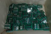
The little PCB's turn up today so i can really get going on getting my RGB dumb icicles done.


Each drop will be a constant 7 RGB leds so that i can use my normal 28v DC i use for all dumb strings.


The little pcb was designed to put the dropping resistors on and provide a simple t-junction from the horizontal power run.
Like this
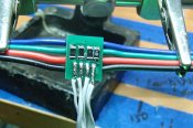
P7140193.jpg


The front has the resistors and drop wiring. The back has the horizontal main cabling
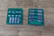
P7140195.jpg


I will be using the C9 covers like this
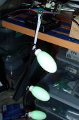
P7140190.jpg


Next step is to design the 3D printer channel to hold each pcb, we are working on 100mm spacing as i have 20M of gutter and a little over 200 of the RGB sections already soldered up.
 

AussiePhil

Dedicated elf
Administrator
Joined
Jun 20, 2009
Messages
1,606
Location
Canberra, ACT, Australia
Update:

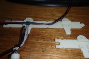
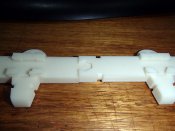
Printed a couple items last night to provide consistent spacing of each vertical drop and to provide mounting for the little PCB's.
P7160202.jpg

already re-designed the spacers a little and now thinking about little clips to hold the pcb's in place whilst silicon waterproofing sets.
 

Kitman

Full time elf
Joined
Oct 25, 2014
Messages
395
Location
Munno Para
You should have added some holes where the channels join so that you can put some zip ties between the 2 so that the join holds together nicely.


Or designed the join between the channels a little different so they click ontop of the next one like lego or something.... just a thought.
 

AussiePhil

Dedicated elf
Administrator
Joined
Jun 20, 2009
Messages
1,606
Location
Canberra, ACT, Australia
Been doing some soldering for the last couple nights, here's another bit of this project.


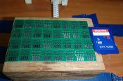
32 x dropper PCB's in a pseudo panel arrangement, double sided tape on the block of wood holds them in place to apply the solder paste, the SD is for size comparison.
P7180205.jpg


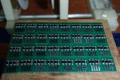
I have solder paste in a syringe and each pad has a little bit added by hand, here's the boards after the paste and 128 resistors placed on them, about 40 minutes. We are ready for the hot air reflow now
P7180208.jpg


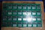
After the hot air reflow that took about 12 minutes it starts to look a lot better.
P7180212.jpg


And off the block of wood to join the others already done...
P7180214.jpg
 

AussiePhil

Dedicated elf
Administrator
Joined
Jun 20, 2009
Messages
1,606
Location
Canberra, ACT, Australia
Kitman said:
You should have added some holes where the channels join so that you can put some zip ties between the 2 so that the join holds together nicely.


Or designed the join between the channels a little different so they click ontop of the next one like lego or something.... just a thought.


Hi Kit,
It was designed to click together to keep the precise 100mm spacing, i've pulled the join fractionally so you can see it in the photo.
at least each section of 800mm will be glued together for strength.
P7180216.jpg
 

AussiePhil

Dedicated elf
Administrator
Joined
Jun 20, 2009
Messages
1,606
Location
Canberra, ACT, Australia
Well another week has passed and I have broken the construction down into stages.


There is around 200 vertical sections of 7 Leds each, fortunately the sections were pre-made about 5 yrs ago.
What i did need to do was solder on a positive voltage tail to go from the bottom of the drop back up to the t-joint pcb.
Here is what around 200 look like hanging on a couple nails
P8100263.jpg


and a close up, the C9 pixel covers are attached to real pixels :)
P8100264.jpg


Next step is to turn each string into a ready to attach vertical drop as shown in the one completed 9 drop section.


P8100267.jpg
 
Top