
Will there be a group buy for these boards an parts?
You are using an out of date browser. It may not display this or other websites correctly.
You should upgrade or use an alternative browser.
You should upgrade or use an alternative browser.
60 channel dmx board
- Thread starter AAH
- Start date
Benslights
Dedicated elf
looking good AAH. will be exciting to see your first set of lights running off your own board.
Timon
Apprentice elf
I didn't see the resistors and caps in SMD being as much of a build problem as the ICs which have such closely spaced leads. I'm looking at getting back into hardware design and the one thing I worry about it building prototypes with SMDs are the IC as I'll need new soldering station, 3D microscope and other items I never needed with through hold components.AAH said:There's about 120 SMD components which makes up almost everything except the 60 mosfets and the connectors. Without fully assembling the boards there is no way for me to test them or to install the firmware. The original firmware will need to be installed via the ICSP programming header but all public release firmware will be via downloads that can be installed via a thumbdrive.
After posting I thought about the programming issue so keeping it as a assembled board is totally reasonable.
Since you have so many SMD have you looked into having that part done on a pick-n-place machine at a board build house at least when the order are larger? Since I haven't done SMD boards I have no idea what it costs so it may not be economically feasible.
I have to ask, how the heck are you adjusting the voltage ranges in each zone using a single supply without dropping a lot of energy in the MOSFets? I didn't think I saw a DC-DC converter in each zone

- Thread starter
- #34
The resistors and caps are actually more of a problem when it comes to loading the board. The board has been laid out with IPC footprints. IPC footrpints are pad sizes and placings that are especially designed for high reliability pick and place followed by reflow soldering. The pads are basically the exact same size and position as the metallic end contacts on the SMD components which has the effect of stopping "tombstoning" which is where the surface tension of the molten solder pulls a small component up at right angles to the board and you end up with something that looks like a tombstone. Hand soldering onto IPC footprints is a bastard to put it politely but it does allow the possibility of machine loading.
I would love to have the boards machine loaded but the last time I had stuff done there was a $600 setup fee as well as the per component loading fee. Each successive batch of boards has a setup fee which isn't as high though. I will be looking at the cost of getting the boards loaded both here in Aus as well as in China but the setup fee really is a bit of a killer.
I've loaded 10's of thousands of smd components and have never used a stereo microscope. A nice fine tip like 0.4mm, 0.355mm or at least under 0.5mm solder, lots of light, fine tipped tweezers and glasses like below are all that's needed. For non IPC footprints and 0805 sized components and 0.05" lead spacing ICs I use the naked eye with no problems.
The voltage reduction is done via PWM which is the same method used to dim lights. It's a pseudo voltage reduction really. As far as the eye and metering it goes it will look and measure as the lower voltage. A 40V 30A rated DC-DC would probably be half the size of the pcb.
[attachimg=1]
Attachments

AAH said:The voltage reduction is done via PWM which is the same method used to dim lights. It's a pseudo voltage reduction really. As far as the eye and metering it goes it will look and measure as the lower voltage.
Alan, I think I understand the scaled PWM method you are proposing, but won't the peak voltage (and therefore current) applied to the load be a problem?
Timon
Apprentice elf
Even though I use to design and build computers and have been around a lot of automated equipment I still love to watch them in action.
Nice, and it's only $54K
The New Pick and Place Machine
And better, I don't even want to ask how much :
http://youtu.be/S8qkaTsr2_o
Nice, and it's only $54K
The New Pick and Place Machine
And better, I don't even want to ask how much :
http://youtu.be/S8qkaTsr2_o
- Thread starter
- #38
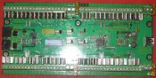
I finally got the balance of the parts in this morning and i thought I'd stick a few components on 1 of the 4 boards that I have part loaded. There's still about 8 components to put on the board but it's time for me to call it a night. I hope to power the board for the 1st time on Saturday and to begin the electrical tests. After everything is working electrically then I get to add a few thousand more lines of assembler to get the firmware sorted. At this time I'm still looking at a launch at the Melbourne mini. I will likely offer a discount to attendees there
Attachments
ewanh
what goes here?
I really wish we had a 'like' button here .....
G
GoofyGuy
Guest
How is this coming along AAH? Im going to need to start setting up my RGB and 2 of these would fit the bill perfectly? No pressure but HURRY UP! Im glad theres guys like you here, as I would have no clue except spend money on getting things going. Your work is great I cant wait to see it in action ( on my house!)
- Thread starter
- #41
Just a little update for those waiting on seeing these boards. At the moment I'm coding madly when I get a free moment away from work. I'm about 1000 lines of code into what I expect to be about 2500 lines of code in the end. Getting my head around 3 different serial data formats happening at the same time and the interrupts associated with them has been giving me some mega headaches. At this stage I'm still looking at releasing the boards at the Melbourne mini.
Alan
Alan
- Thread starter
- #42
Two lots of bad news. Last weekend I discovered that the Melbourne mini was a week earlier than I expected so I lost a week of development that I thought I had. What is even worse news is that the development isn't playing nice at the moment. I have a bug with my dmx code so that it is only logging the data from the 1st 10 channels and it is skipping almost half the packets. With the prep work that I need for what I'm taking down to the mini I have now conceded that I now have no hope of having the aahmega60 complete ready to show then. I will have a board or 2 with me but I don't expect that it will have all of its features up and running. It's been a frustrating few days for me over the last few days as my hairline and the guys in chat could tell you.
Alan
Alan
ewanh
what goes here?
no problems Alan, we appreciate all the effort you are putting in. If I knew anything about coding for DMX I might offer to help... but I don't.
Maybe we coudl have an "AAHMEGA60 Launch Party" later in the year?
Maybe we coudl have an "AAHMEGA60 Launch Party" later in the year?
Benslights
Dedicated elf
Allan im sure every one is happy to wait as we all know it will be worth it.
Keep up the good work.
Keep up the good work.
jeromej
Newbee, and learning the hard way!!!
I just finished reading this.
I want even pretend to understand 1/2 the stuff that has been spoken about, but they sound fantasic.
I just don't know how you guys understand all this technical stuff and how you are able to put it all together and make it work
It's magic in a box!!
My hat is off to you
Look forward to seeing one working.