Best Soldering Practice for power injection & connecting strips

Thebruhhh

New elf
Joined
Sep 29, 2020
Messages
20
Hey everyone!

I have all my supplies and am doing a test run in my bonus room before venturing outside.

I am mounting aluminum channel and putting in WS2812B 5v LED strips (30 LED/meter) and using a small 22 gauge wire for power injection. That gauge wire I know could be bigger, but nothing will work inside this channel. Space is maximized.

I am running into a dilemma:

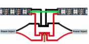
What is the best way to solder 2 LED strips together along with power injection? Does anyone have any reference pictures of what they did? I have the drawing of how I need to wire it, but if I did it the way I was going to you'll see a gap into between the strips and I want to be near seamless as possible.
 

Attachments

  • test.png
    test.png
    46.1 KB · Views: 31

Jorge Bolivar

Full time elf
Joined
Nov 17, 2019
Messages
100
Location
Cleveland, Ohio
@Thebruhhh
I did this once.
I joint the strips first, copper tips to cooper tips. Ten I do strip a portion of the insulation whitout splice the cable and soldered to the + / - and do the best to folded toward the back of the strip around the 3rd node after the joint. I can't notice the cable at all. I no have a picture with me.
 

TerryK

Retired Elf
Joined
Feb 9, 2020
Messages
655
Location
West Central Ohio
I do not have any strip props yet (in the forecast) but I would use an overlap joint. A butt joint can be used but an overlap joint gives a bit more strength to the splice. Your strip needs pads on the bottom and top for this to work of course. Use a jig or clamp to hold the strips in alignment while soldering; just the strips at this point, not the wire yet.

As Jorge mentioned, for the power injection wire, determine where the solder point will be and remove the insulation at that point but do not cut the wire. I would think a 1/16th of an inch, maybe an 1/8 will do and remember, soldering heat will melt back the insulation further. Preform the wire to a Victorian U or V before soldering. Less fighting the wire that way when attaching it to the strip joint.

Pre-tinning the solder pads will also help and with pads on the face and rear the power injection wire can be on either side as well.
 

Thebruhhh

New elf
Joined
Sep 29, 2020
Messages
20
@Thebruhhh
I did this once.
I joint the strips first, copper tips to cooper tips. Ten I do strip a portion of the insulation whitout splice the cable and soldered to the + / - and do the best to folded toward the back of the strip around the 3rd node after the joint. I can't notice the cable at all. I no have a picture with me.

Thank you that gives me a good visual. @Jorge Bolivar to the rescue!
 

Thebruhhh

New elf
Joined
Sep 29, 2020
Messages
20
I do not have any strip props yet (in the forecast) but I would use an overlap joint. A butt joint can be used but an overlap joint gives a bit more strength to the splice. Your strip needs pads on the bottom and top for this to work of course. Use a jig or clamp to hold the strips in alignment while soldering; just the strips at this point, not the wire yet.

As Jorge mentioned, for the power injection wire, determine where the solder point will be and remove the insulation at that point but do not cut the wire. I would think a 1/16th of an inch, maybe an 1/8 will do and remember, soldering heat will melt back the insulation further. Preform the wire to a Victorian U or V before soldering. Less fighting the wire that way when attaching it to the strip joint.

Pre-tinning the solder pads will also help and with pads on the face and rear the power injection wire can be on either side as well.

thank you for the extra detail. I’ll have to google what a Victorian U or V specifically looks like with wiring.

appreciate all the input everyone
 
Top