Blowing Fuses on Pixlite 16 MKII

Max Kabilafkas

Apprentice elf
Joined
Dec 19, 2020
Messages
55
Hi

I recently got my first bulk order of pixels and am testing everything out. However I keep blowing the 4A fuses that come with my Pixlite 16 MkII controller.

In the last test I did, I had a single 100 node 12v string of pixels plugged in to one of the outputs. It worked fine then as I was changing the colour of the pixels they all stopped working. I switched the string to another output and it worked again, and again blew the fuse after trying to change the colour a few times.

Why would that single string be pulling such a high current from the controller? It is receiving power directly from the board.

Thanks

Max
 

uncledan

Senior elf
Generous elf
Joined
Dec 27, 2014
Messages
545
Location
Buellton California
Easy solution is to adjust the brightness in the Advatek Assistant down to 50% or less. As Daryl mentioned you are exceeding the limitations of the board and the fuses are blowing for a reason.
 

Max Kabilafkas

Apprentice elf
Joined
Dec 19, 2020
Messages
55
Right ok.

So I can see that when I increase the number of pixels the current increases. Do I have to keep decreasing the brightness of my pixels as the string length increases? Or does the additional power I supply through power injection not get to the fuses?
 

uncledan

Senior elf
Generous elf
Joined
Dec 27, 2014
Messages
545
Location
Buellton California
Decrease the intensity or power inject are your two options. Remember data and V- continue through the whole strand. Only break the V+ when you power inject. No reason to run at 100% intensity so I find it easiest to just limit the intensity at the controller level myself. I have runs of 200+ 12v nodes with no power injection. Individual results will vary. The V+ is fused on the Pixlite, this is why you break the V+ connection at the end of the first part of nodes that's powered through the board
 

Nojoy

Full time elf
Joined
Aug 9, 2020
Messages
110
Unrelared to your fusing issue, Does the pixlite mk2 still have 170 pixel per output limitation as well?
 

darylc

404 darylc not found
Joined
Dec 8, 2012
Messages
1,146
Unrelared to your fusing issue, Does the pixlite mk2 still have 170 pixel per output limitation as well?
The Pixlite never had this limit, even the original ones supported 340 pixels per port.
 

Nojoy

Full time elf
Joined
Aug 9, 2020
Messages
110
@darylc sorry was thinking of the Pixlite 16 Plug & Play in expanded mode. But found the answer in their manual, all good
 

Max Kabilafkas

Apprentice elf
Joined
Dec 19, 2020
Messages
55
So is this thinking correct?

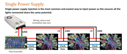
In this snippet from the 101, if we assume each of those strings is a 100 node 12v string, the total current at 100% brightness is about 16.65A. So I would need to drop the intensity to around 25% in order to not blow my 4A fuse?

1629087781694.png

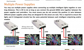
But if I do the multiple power supply method as below, then as only 100 nodes are connected via the V+ line to the fuse, the current going through the fuse at 100% brightness is 5.55A, so I would only need to drop my intensity to 70% to get below the 4A mark


1629087923844.png
 

i13

Dedicated elf
Joined
Jul 5, 2013
Messages
1,172
Max Kabilafkas, both of the diagrams that you posted will get around the current limitation because the current flows directly from the power supply to the injection points. The only current that needs to be limited is the current that flows through the PixLite itself. In your first diagram, if you cut the positive between pixels 50 and 51, you'll only power the first 50 pixels through the PixLite. Pixels 51 to 100 will be powered from the first injection point because (unlike data) power is not directional. Going into further detail, it might also be sensible to cut the negative between pixels 50 and 51 so that the current from the additional pixels doesn't flow through the negative trace on the controller. Don't do this in the second diagram; this is not a problem in the second diagram because each power supply has its own independent current path. Cutting the negative here in the second diagram will stop the additional pixels from working because the negative is used as a reference for the data signal.

In the second diagram, you may as well power in both directions from the injection points. It reduces the required number of injection points and/or the maximum distance from each injection point to its furthest pixels. Like in the first diagram, using this technique can further reduce the number of pixels powered through the PixLite.
 

KiwiPhil

Full time elf
Joined
Dec 17, 2017
Messages
165
Location
Boondall, Brisbane
FWIW I run my pixels out of my pixlites at 25%, any brighter and they look more white and lose colour definition, I think pixels actually look much better the lower you go
 

christmasdave

Full time elf
Joined
Dec 10, 2020
Messages
107
Location
NSW South Coast
FWIW I run my pixels out of my pixlites at 25%, any brighter and they look more white and lose colour definition, I think pixels actually look much better the lower you go
Have to agree with this. I’m still starting out setting up for my first year and have started running tests on the house. I started at 50% and am down to 30%. still finding that pretty bright!
 
Top