Answered How to run sequence and get the outputs running

Micro16

New elf
Joined
Dec 29, 2021
Messages
13
Hello, still some newb questions... been working on and off on my setup and I think I can see some light at the end of the tunnel. So I've got a baldrick 8 setup and working. I've got my props wired. I've got a layout and sequence setup in xLights. I've got FPP setup on a Beaglebone Black.
I think what I'm mainly missing is, how do I put the show / sequence onto the BBB, and then how do I have that communicate with the Baldrick to actually run the show and give some outputs? What do I need to configure and where?

Should the baldrick and/or the BBB be wired into the router / switch at all times for the next few weeks?

Maybe a stupid question and as such I think I know the answer, but can I just have the BBB connect directly to the Baldrick via network cable?
 
I think what I'm mainly missing is, how do I put the show / sequence onto the BBB, and then how do I have that communicate with the Baldrick to actually run the show and give some outputs? What do I need to configure and where?
From xLights

Tools - FPP Connect

This will upload your sequences and configure FPP to output to the controllers.
You will need to set UDP Out to All on that dialog for the show player FPP


Should the baldrick and/or the BBB be wired into the router / switch at all times for the next few weeks?
That would be the simplest. Means you don't have to set anything up specifically.
 
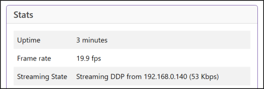
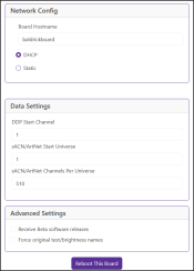
Ok, so made some good progress now. I have them both on the network, and they are communicating (baldrick and fpp)
1733670743448.png

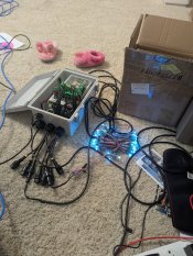
However, my test string is just sitting idle with all blue state, same as when I first turn them on with no FPP running (don't ask me why, seems almost like a test, but I have no test configured nor enabled, that I know of).

PXL_20241208_152026613.jpg

Any thoughts as to where to look?
 
Looking at the pic of the pixels wired up I suspect that the data direction is wrong. Those little 3 pin JST plugs are used with the opposite polarity to what is logical. The female end on the pixels is the input. The pixels also have a Di (data in) marked on the pcb that you may be able to trace.
 
Looking at the pic of the pixels wired up I suspect that the data direction is wrong. Those little 3 pin JST plugs are used with the opposite polarity to what is logical. The female end on the pixels is the input. The pixels also have a Di (data in) marked on the pcb that you may be able to trace.
DI is visible and is on the female end as you suggested, and this is the end that I have connected to the board. For funsies I tried the other way, and the result is the same, which is, to say, not exactly what I might have expected. In both cases, holding down button 2 or button 1 did not yield a test mode. FPP is not active at this time, to try and rule out anything on that side. Right now, it's just the baldrick board, 100 spare 12v pixels on port 5, 12v PSU on P5-8 and 5V PSU on P1-4 but nothing currently connected to those. I do have a small amount of spare 5Vs that I could throw on for testing if particularly interested.
 
Last edited:
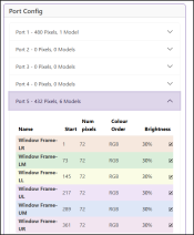
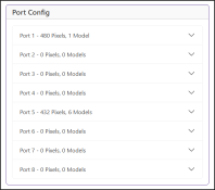
Can you shoot a pic of the output configuration? Not getting a test mode has me thinking that there may not be any outputs defined.
 
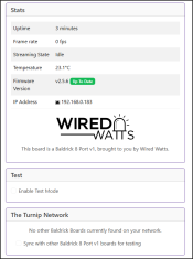
So I noticed something a little strange, but repeatable tonight. When I unplug the enclosure (pull the main power plug), the pixels flash before going out. If I have a test mode turned on when this occurs, you can see the test mode for a few milliseconds. If I choose green, I can see green flash. I also noticed after having it on rainbow, a multicolor flash. It leads me to think that for some reason, data is just stuck and not getting pushed out / refreshed, but just before going down it refreshes for a cycle and then goes down. Not sure how to resolve it, but hopefully this helps Dom a bit.

Aside, just in case this was the outputs info you were looking for Alan, here's the 'outputs' config in FPP:
1733717191782.png
Controller in xLights
1733717790151.png
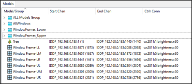
Models in xLights
1733717894192.png
 
Last edited:
Last bit first.
Can you unplug the ethernet connection and see if that allows you to get the test mode to work by holding down button 1 or button 2 for 3s. If it works then but not while the ethernet is plugged in I'd be looking for something sending blank/zero data to the lights. That could be xlights with output to lights enabled or an FPP instance.

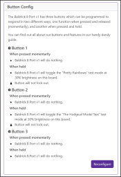
Back to test mode not doing it's stuff now. Have you tried both holding down the S1 or S2 button for 3s and also the radio button on the web interface?

I haven't actually checked to see if data gets pumped out while the board is idle but when data is being sent out I'd expect to see maybe 0.7V DC between the 0V and data pins on the connectors. The actual voltage can vary depending on the number of pixels, the global brightness set for them and the colours being sent out to them.
 
Unplugged Ethernet from Baldrick port, tried test mode with button 1, button 2, button 1+2, no effect.
Computer is off for the night but I noticed earlier that holding down the buttons on the board actually trigger the same effect as clicking the box in the web UI. If you hold the buttons, the web box will toggle.
 
This thread is marked as solved. An answer might not be needed anymore.
Back
Top