My kulp box setup - please check wiring diagram for correctness

janastas

Full time elf
Joined
Nov 30, 2020
Messages
120
Hi All,

So a few weeks back I ordered the Kulp K40D-PB plus another four smart receivers:

https://kulplights.com/product/k40d-pb/

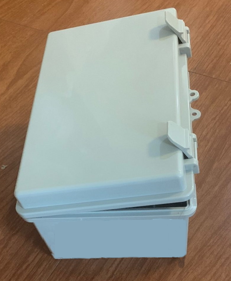
I currently have the following setup within an ABS enslosure
Pic of setup is as follows:


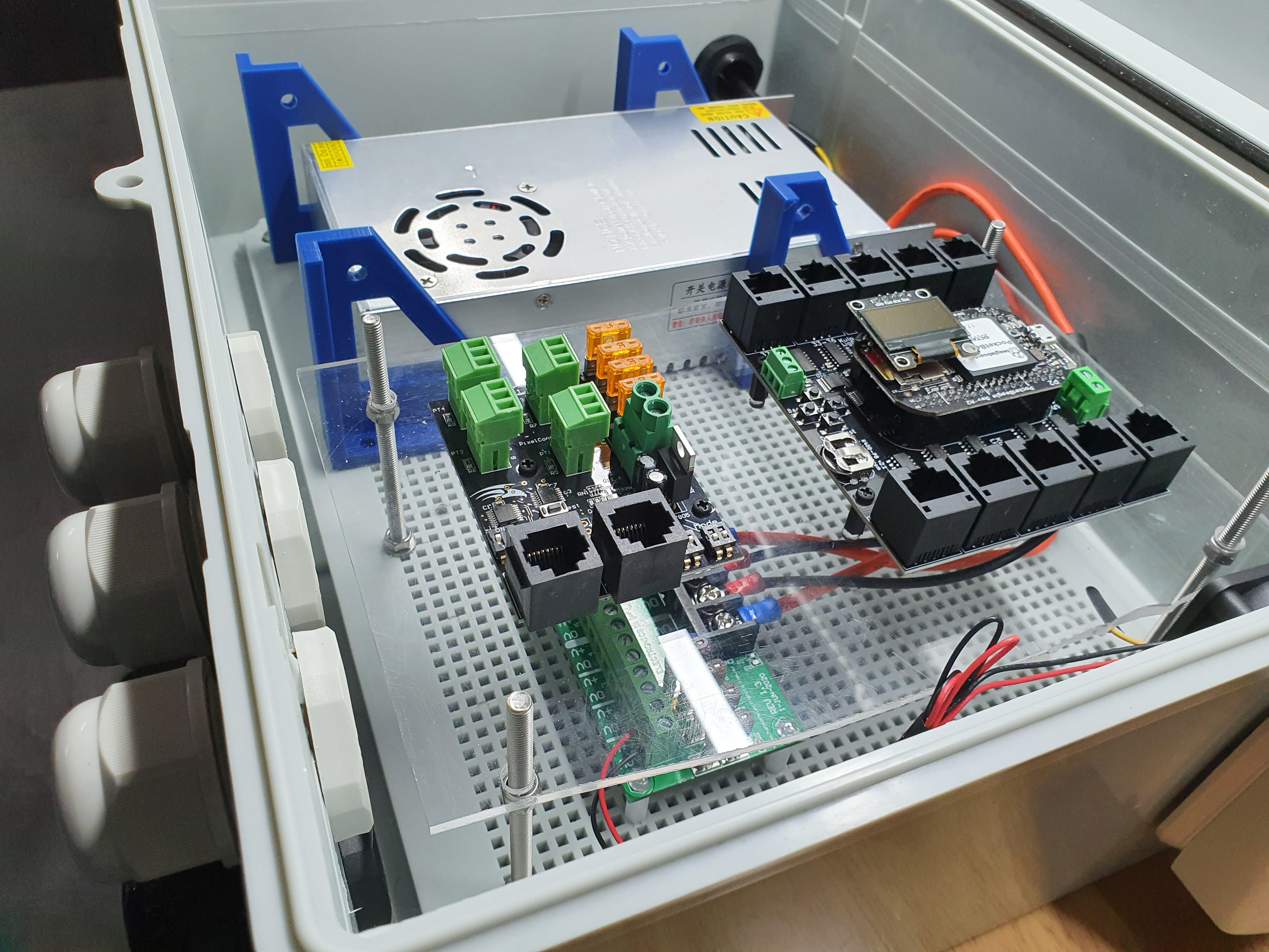
I've tested all the smart receiver ports via FPP and the on board test button and everything seems to work fine.

My query is about how best to utilize the power distro board for power injection.
My understanding is that each smart receiver port can handle 1024 pixels? Is that correct?

If so I'm wondering if the below setup on a single port of the smart receiver will work.
The aim is to utlise the power from the smart receiver port for the first 50 pixels then use a power tee that has the positive not connected from the first set of 50 pixels.
The power going to the next 50 and so and and so forth will come from the power distro board.

See the diagram below for what I want to do.


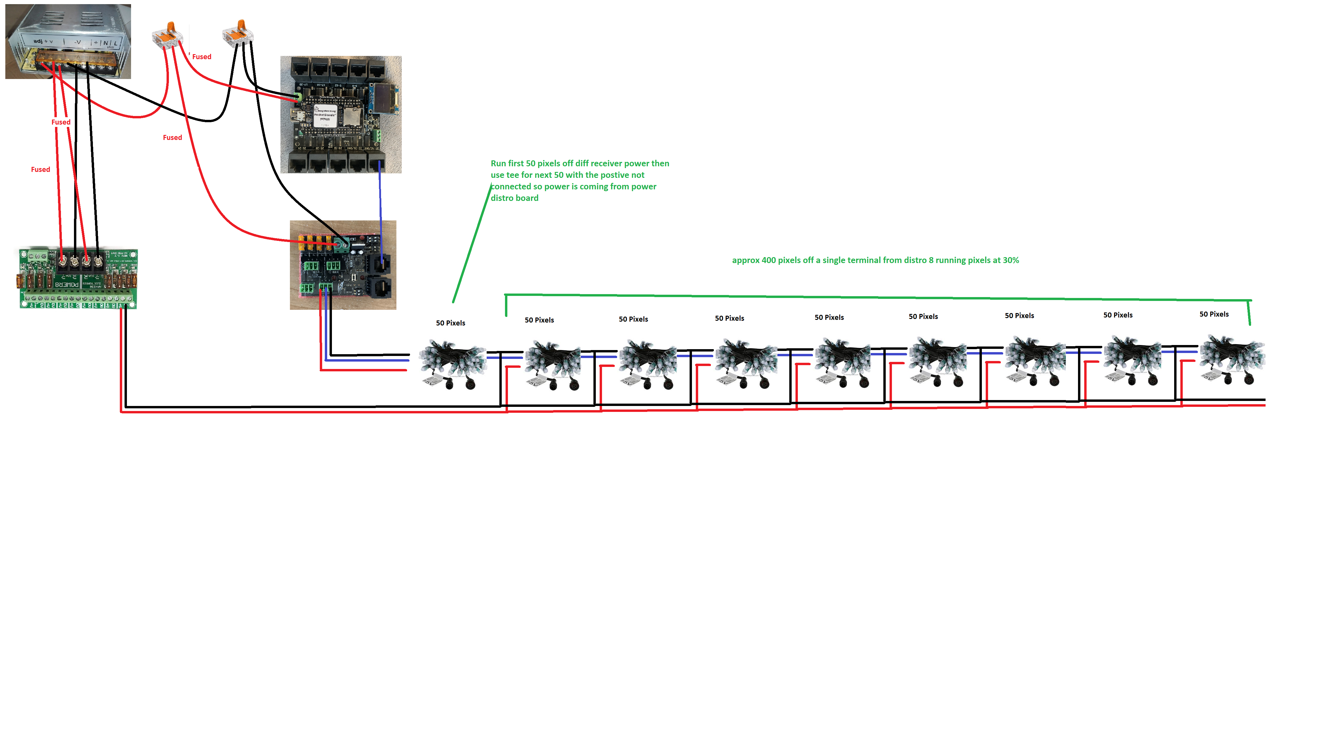
I'd appreciate and feedback to confirm that the above diagram will work (Note that I've deliberately only put 9 batches of 50 pixels and they will be running at 30% brightness))
 
Last edited:

AAH

I love blinky lights :)
Community project designer
Joined
Dec 27, 2010
Messages
4,191
Location
Eaglehawk
The wiring to the Power8 is incorrect. The 2 0V connections are in the centre and the 2 5V connections are on the outside.
If you're running at 30% then you can get away with a power injection point every 100 pixels.
There's 6 potential connection spots for power coming from the power supply. Each side of the 3 V+ and V-. As long as you're not pulling more than 30A from any single output you can just run the K40 and receiver direct from the power supply.
 

janastas

Full time elf
Joined
Nov 30, 2020
Messages
120
The wiring to the Power8 is incorrect. The 2 0V connections are in the centre and the 2 5V connections are on the outside.
Yep thanks, the physical wiring is correct on the power8 distro (I double checked it), I just didn't look close enough when I was doing the diagram in MSPaint!

If you're running at 30% then you can get away with a power injection point every 100 pixels.
Gotcha, thanks that will save me having to power inject every 50 pixels.
Just to confirm in the diagram I've specifically called out at the first 50 pixels will be powered by the smart receiver port then the rest of the pixels will be powered by power tees. That wiring all looks correct?

There's 6 potential connection spots for power coming from the power supply. Each side of the 3 V+ and V-. As long as you're not pulling more than 30A from any single output you can just run the K40 and receiver direct from the power supply.
ok thanks. The power8 distro is using 4 of the 6 connection points.

The K40 and receiver will use the other two but just wanted to have one set of cable instead of two coming from the power supply hence the wago lever nuts someone else in the ABS box
 

i13

Dedicated elf
Joined
Jul 5, 2013
Messages
1,172
If you can get away with power injection every 100 pixels, you should be able to get away with power injecting in both directions so that no pixel is more than 100 pixels away from an injection point. Data is directional but power isn't. If you connect the positive in both directions at the injection point, you can have an injection point every 200 pixels. All pixels in the run are on the same power supply in your diagram but if they weren't, you'd need to cut the positive line in the pixels half way between the injection points so that you don't connect the power supplies' positive outputs together.

Regardless of whether you're going to inject in both directions or not, if you're planning to have 100 pixels away from the injection point, it would be a good idea to bench test this for voltage drop and incorrect colours. Not all pixels are created equal; the limit will depend on their current draw, the wire thickness and wire length between them. You'll also need to consider that there will be voltage drop in all wires in your diagram. The voltage that reaches the pixels at the injection points will already be below 5V. Keeping the cables short and thick helps.
 

janastas

Full time elf
Joined
Nov 30, 2020
Messages
120
Thanks for your feedback all. This all helps a lot and I can now concentrate on power injection for my props but also building more props now.

The last question I had was just around the calcs for the number of pixels I could technically run off this setup.

So for the power supply I have:

SC-400-5-70: 5V 70A 350W
Under the assumption that the max load I'll be applying is 75% = 350W * 75% =~ 260W

5V pixels - watts per pixel at 30% brightness = 5V * 0.06A (60mA) @ 30% = 0.09W per pixel

So 260W / 0.09W = 2,888 pixels in total using this enclosure setup

I haven't taken into consideration the power required to run the K40D-PB or the smart receiver but guessing I could round down to about 2,500 pixels to be safe?

If anything doesn't look right above please let me know.
 

i13

Dedicated elf
Joined
Jul 5, 2013
Messages
1,172
You must be using WS2811-compatible pixels because you're using receivers that provide that data type. You can therefore change your calculation to 55.5 mA per pixel. 60 mA is a more realistic value for WS2801 and dumb RGB. In reality, the pixels are likely to draw even less than 55.5 mA at 100% brightness. The exact figure varies but WS2811-compatible pixels can't exceed 55.5 mA.
 
This thread is very old. An answer might not be needed anymore.
Top