New to LED Display/Show

EduJime

New elf
Joined
Dec 20, 2020
Messages
1
Hello everyone,
This is my first time ever trying LED’s but my wife wanted them this year so I had to learn quickly in about a month.
Here are my current problems:
- 3 sections are flickering
- Sometimes 1 section gets stuck and won’t respond to my commands, have to unplug the power and star over.
- Just a window works with Xlights I’ll have to learn xLights for next year.

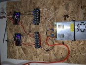
I’m using:
• 2 no brand 12v power supplies a 30Amps and a 50amps
• 20awg cables
• 3 QuinLED-Dig-Quad controllers
• 12v Pixel LED’s

39CE1115-974C-4A8A-9EAE-DC6DF9503AEA.png
12C9DAD5-3CDE-46B7-8C52-858B3F45AAC8.jpeg
E87DCFC5-8A31-4B1C-8CC8-00E9B90B2D4B.jpeg
 
Last edited:
Welcome to ACL.
The flickering can be a number of problems. It can be cables bundled up close together and getting interference from other cables in the bundle, the distance between controller or a pixel and the next pixel is too far a break in the ground/0V wiring.
Pixels latching on is quite often a symptom of low voltage at that point. It's generally towards the far end of the strings and will occur when there is a peak in the current caused by lots of lots in the string turned to high brightness at the same time. A simple fix for this is within xlights set the brightness for the prop to a reduced value like 70 or 80%. The better option is to provide some power injection or some heavier power cables.
First time I've seen those QuinLed controllers. They look a fairly nice option.
 
I researched the controller a bit. Rather odd I think that Ports 1 and 2 share a fuse as does 3 and 4. I'm curious as to the reasoning behind that design decision. The web information on the device also seems to place significance on 1 Oz vs. 2 Oz copper on the board. Board copper is not a subject that is typically discussed at the consumer level in my opinion.

The wiring in the photo is too small. Whether the supply in the photo is the 30 Amp. or 50 Amp., you need heavier and additional wires between the supply and distribution terminal block. Without additional information detailing your display design and implementation, Alan has most topics covered well I think. I would suggest that you read (or re-read) ACL's 101 Manual. The manual has fundamentals pertaining to voltage drop, wire sizing, and power injection that should help you better understand electrical implementation of the display.

As you indicated that you are just starting, depending upon how your display grows, might you research Falcon controllers? The QuinLEDs do not show very often and the Falcons seem to be everywhere. A much larger support group for problem solving.
 
it has 5 fused outputs, with some extra screw terminals.

it only has 4 pixel outputs, so its not a big deal.

It all depends on the load. Most are fused at 5 Amp. My loads will be 7.5 Amps. I'm going to an external fuse block, and just using ground and signal wires from the controller for each string.
 
it has 5 fused outputs, with some extra screw terminals.

it only has 4 pixel outputs, so its not a big deal.
I rechecked. There is a section of their webpage where the positive terminals are called channels. I assumed channels meant ports, not. The unit has 4 data terminals which produces 4 'channels' if one uses 3 wire pixels. Their webpage does not go into detail regarding configuration but indicates the controller only has 2 'channels' if one uses 4 wire pixels. As to the positive terminals, 1 and 2 share a fuse, 3 and 4 share a fuse, terminals 5 through 7 each have individual fuses. A specification I was curious about but did not see was refresh rates possibly versus number of pixels on an output.
 
Back
Top