
I am currently designing an octoscroller board with a built in real time clock so that it can be scheduled without access to the internet. It will use the same footprint as the existing octoscroller and should be ready for shipping in a few weeks.
Navigation
Install the app
How to install the app on iOS
Follow along with the video below to see how to install our site as a web app on your home screen.
Note: This feature may not be available in some browsers.
More options
You are using an out of date browser. It may not display this or other websites correctly.
You should upgrade or use an alternative browser.
You should upgrade or use an alternative browser.
Octoscroller with rtc
- Thread starter AAH
- Start date
Voltorb
New elf
Were you able to test the new design? Any feedback?
- Thread starter
- #4
PRE-SALE ON NOW
The Octoscrolla V1.5 board is now available on my site as a pre-sale special. Any purchases of it prior to the shipping date of the 1st boards on Thursday 13th August 2015 will get a special price and the board shipped for free. The boards will be fully soldered and tested and ready to go. It will come in 2 versions. 1 with no Real Time Clock (RTC) and 1 without. The RTC can't be fitted after the board is purchased.
The board is called Octoscrolla because the Octoscroller name and concept was developed by Trammel Hudson (some background information on it can be found at http://www.nycresistor.com/2013/09/12/octoscroller/)
Both the octoscrolla and octoscroller can drive up to 64 P10 pixel panels.
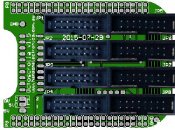
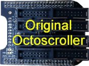
The differences between the Octoscrolla and Octoscroller can be seen in the 2 photos below.
-The 2 ground test points are labelled on the overlay
-The spacing between the connectors for the P10 panels has been increased which allows labeling for the connectors to be seen.
-A real time clock can be fitted (at time of manufacture) that mounts under the Octoscrolla and solders to 2 headers between JP1-JP2 and JP3-JP4
-The 5V connector at the bottom left corner has now had a 3rd pad added which allows a 5mm terminal to be fitted so that the BBB can run from the same power supply as the P10 panels.
-The number of pcb vias has been reduced to 15 from the original 54 through changes to the routing.
[attachimg=1]
[attachimg=2]
http://www.hansonelectronics.com.au/product/octoscrolla_with-rtc/
http://www.hansonelectronics.com.au/product/octoscrolla_without-rtc/
Info on the octoscroller can be found at http://auschristmaslighting.com/wiki/Octoscroller
The Octoscrolla V1.5 board is now available on my site as a pre-sale special. Any purchases of it prior to the shipping date of the 1st boards on Thursday 13th August 2015 will get a special price and the board shipped for free. The boards will be fully soldered and tested and ready to go. It will come in 2 versions. 1 with no Real Time Clock (RTC) and 1 without. The RTC can't be fitted after the board is purchased.
The board is called Octoscrolla because the Octoscroller name and concept was developed by Trammel Hudson (some background information on it can be found at http://www.nycresistor.com/2013/09/12/octoscroller/)
Both the octoscrolla and octoscroller can drive up to 64 P10 pixel panels.
The differences between the Octoscrolla and Octoscroller can be seen in the 2 photos below.
-The 2 ground test points are labelled on the overlay
-The spacing between the connectors for the P10 panels has been increased which allows labeling for the connectors to be seen.
-A real time clock can be fitted (at time of manufacture) that mounts under the Octoscrolla and solders to 2 headers between JP1-JP2 and JP3-JP4
-The 5V connector at the bottom left corner has now had a 3rd pad added which allows a 5mm terminal to be fitted so that the BBB can run from the same power supply as the P10 panels.
-The number of pcb vias has been reduced to 15 from the original 54 through changes to the routing.
[attachimg=1]
[attachimg=2]
http://www.hansonelectronics.com.au/product/octoscrolla_with-rtc/
http://www.hansonelectronics.com.au/product/octoscrolla_without-rtc/
Info on the octoscroller can be found at http://auschristmaslighting.com/wiki/Octoscroller
Attachments
bluzervic
65,768 Channels, 185 Universes
I would be interested in 1 with RTC.
Do enlighten me with additional info on what else I may need.
Here is my list so far
1. P10 panels
2. Beaglebone black
3. cables
4. power supplies.
5. Octoscroller ( your board)
Would also like to know how this interfaces with SEQ software like LOR or XL4.
This will be for a 2016 project.
Once again I have Noob status")
-Blu
Do enlighten me with additional info on what else I may need.
Here is my list so far
1. P10 panels
2. Beaglebone black
3. cables
4. power supplies.
5. Octoscroller ( your board)
Would also like to know how this interfaces with SEQ software like LOR or XL4.
This will be for a 2016 project.
Once again I have Noob status
-Blu
- Thread starter
- #6
As you are in USA Vic it's probably easier to grab via http://falconchristmas.com/forum/index.php/topic,2671.0.html as voltorb is running a pre-sale using the boards I designed over in Yankeeland.
You appear to have got the hardware list right. 1 350W 5V power supply will probably do up to about 50 P10 panels so you can probably get away with 1. There are usually interconnect cables supplied with the P10 that connect to the power supply and from P10-P10 so the only cables that are required are ones from the octoscroller to the P10.
Xlights 4 has built in support for the P10 panels already and I know that some people are using P10's with Vixen. Theoretically you could sequence with any software as the P10 is simply a matrix with 512 pixels in it arranged in a 32x16 grid. Allocating the channels of a fully stacked 64 P10 matrix works out to nearly 200 universes so that could be a nightmare.
Hi Alan.
Are you able to confirm which side is Pos & Neg for the 5v connector that has been added? A diagram would be most helpful as I don't want to blow it up!
Cheers, Graham
Are you able to confirm which side is Pos & Neg for the 5v connector that has been added? A diagram would be most helpful as I don't want to blow it up!
Cheers, Graham
- Thread starter
- #8
The 2 terminals are labelled in pretty tiny text with 0V and 5V. The 0V or -ve is the the centre of the board and the 5V which powers the BBB is to the outside of the board. You can see it on the picture above that doesn't have the connector installed.
Daniel1973
Full time elf
Thanks Alan
Got my delivery today,
Daniel
Got my delivery today,
Daniel