P2, P8 & P12

Porsche

Full time elf
Joined
Nov 7, 2012
Messages
165
Location
Perth, Piara Waters
Hi guys, im just looking at some easier wring options for the future.
I know the P2's Im using are UNFUSED.
But J1's are saying the 8's and 12's are fused.
At the moment I don't run power through my P2's to the string, they are separately power.
But am I right in understanding the 8's and 12 units they have you can run the actual power through the unit to power the strings because they are fused. (until power injection is needed of coarse).
 
Hi Porsche,

Yes this is the case with the P12 and i think the P8 is the same. The P12 has 2 power inputs so you can feed power in from 2 supplies. (each drives 6 outputs)
 
Another thing to consider is that the new P12D has differential outputs on it which allows longer distances to pixels without the need for null pixels. There are also different receiver boards for the "far end" from the P12D that are required but very nicely priced depending on what you need at the pixels themselves. Different receivers have regulators on them for power at the pixels and there is a new nPWR-DP2 which has 2 fused high current outputs.
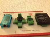
new J!Sys.jpg

This link can help with the lower board which is the P12:
https://auschristmaslighting.com/th...ith-the-j1sys-ecg-p12r-controller-guide.2232/

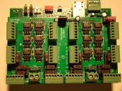
The upper board has 2 power input connectors that are fused at 30 amp each (one for each bank of 6 outputs).
Each output is fused at 7.5 amp as well.
DSC02428.JPG
 
Information and specs on the J1Sys stuff is tough to come by unfortunately. I have been bugging Ed for info so that it can be written up for people (which I would gladly do for free if only the data was made avavilable).
Here is the basics for it which is not much>

F14 – very important – only install if the power on P13 is less than 38V. this is the connection for the onboard OKI and the feed down to the P12S. ok course both have one more connection between them and use but it is safest to remove if using some large power voltage. Most people will use 12V or 24V and they should install F14 with the supplied 3A fuse.

K1 – this is the jumpers for the 5V regulator on the P12D to power the differentials. Three logical settings: open if not using ANY differential, 1-2 & 3-4 if P13 is feeding 12V or 24V nominal, 2-3 if P13 is a clean 5V.

Jumpers below each IC are labeled SGL / DIFF. you place TWO jumpers from the center out. To the left for Single Ended (normal CMOS/TTL levels), to the Right for Differential output.

Each string connector uses up to 6 wires:

G – Ground
C+ - Clock Differential+ if set to DIFF, Clock CMOS/TTL if set to SGL
C- - Clock Differential- if set to DIFF, no connection if set to SGL
D+ - Data Differential+ if set to DIFF, Data CMOS/TTL if set to SGL
D- - Data Differential- if set to DIFF, no connection if set to SGL
+V – Power distribution, usually 5V, 12V or 24V

Examples:

To directly hookup a WS2801, set the jumpers to SGL and use G, C+, D+, +V pins

To PPX hookup a WS2801 to feed a PPR-A etc, set the jumpers to DIFF and use G, C+, C-, D+, D-, +V with G and +V using double wires (the pairs)

To directly hookup a WS2811,set the jumpers to SGL and use G, D+, +V pins

To PPX hookup a WS2811 to feed a PPR-A etc, set the jumpers to DIFF and use at least G, D+, D-, +V. but it is ok to wire the C+, C-. they just won’t be used.


Biggest improvement with theP12D is the differential outputs which will let you get distance from the controller to the pixels with using receivers at the pixels. This improves the data transmission quality and possibly eliminate the need for null pixels in a string.
Also the 12D has some future things being built into it for DMX and other things down the road too.

I have yet to get mine hooked up but too busy with the season right now.
 
Back
Top