Point of use power injection voltage conversion

AussiePhil

Dedicated elf
Administrator
Joined
Jun 20, 2009
Messages
1,606
Location
Canberra, ACT, Australia
this is focused on xx to 5V at the moment.

It is a lot easier to deal with a higher voltage and then convert down to 5v at the point of demand ie your string of pixels.

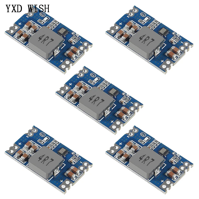
I ordered these little units last month and they arrived today
PC060339.jpg

That is a xx to 5v at 5A buck convertor!!!!! it's quite tiny and the general chat consensus was maybe an amp or two before fire

Time to test, one bench power supply some 32x020 cable on each side and an electronic load.
Sorry no thermal camera, finger tips for temp :)

At 12v input and 4.9v out few about 10 minutes i had no issue holding it
PC060341.jpg

So set the load to 4A and started to wind the input voltage up. At this point it did start to get hot... the IR gun got a peak reading around 70c
PC060343.jpg

Next was the low volt limit - surprisingly this worked all the way down to 5.8v and only at 5.7 did output voltage drop
PC060346.jpg


Set it back to 12v input and 5A current

PC060348.jpg

At this point it's had a solid 30 minutes @5A and i can still hold it for a bit, it's hot but not burning

Conclusion:
Excellent even derated to 4A they are more than enough for a string of pixels
These little units cost me ....... around $2.00 each!!!!
They will make great point of use conversion units. will pot one in epoxy though and retest
They show over 1/4 million in stock :)

Cheers and I hope this helps someone, i'll do some more testing and prepare a usage guide for them.
 

Ltmup

Full time elf
Joined
Feb 1, 2020
Messages
101
would be interested to see how they would go with 31v to 12v,
 

darylc

404 darylc not found
Joined
Dec 8, 2012
Messages
1,146
I used to do a lot of down converting at the power injection point, from 24v to 5v. The problem was eventually the DC-DC converters failed and put 24v into my pixels and killed them. One season I lost about 100m of ws2812b 5v strip

Other time I lost my entire P10 matrix

... be careful ...
 

AussiePhil

Dedicated elf
Administrator
Joined
Jun 20, 2009
Messages
1,606
Location
Canberra, ACT, Australia
I used to do a lot of down converting at the power injection point, from 24v to 5v. The problem was eventually the DC-DC converters failed and put 24v into my pixels and killed them. One season I lost about 100m of ws2812b 5v strip

Other time I lost my entire P10 matrix

... be careful ...
Daryl, goes to prove that not all convertors are the same, I lot of my display also used 24v->5v 10A and 20A waterproof convertors, I have had a couple fail over the years and they failed open circuit and well unbranded ebay/ali items.
Every single controller i've used has been powered via a point of conversion unit.

I have tried to kill this little one pretty hard, got it up to 7A of output and it just damn well grinned at me, got it running a 100 count string of pixels at the moment and the thing is barely above ambient room temperature.
it run 3hrs at 4.5A continuous load nearly 90% capacity rating
 

AussiePhil

Dedicated elf
Administrator
Joined
Jun 20, 2009
Messages
1,606
Location
Canberra, ACT, Australia
One more test - what happens one a short circuit or current overload effectively,

they shut down till powered off and back on.
 

Freman

Uh Oh Elf
Generous elf
Joined
Aug 9, 2021
Messages
118
Hi Friends,

Phil was kind enough to send one of his modules up to me for me to abuse.
The module appears to be based on a JW5068A driver (https://arduino.ua/files/1903051031_JoulWatt-Tech-JW5068A_C371422.pdf)
Depending on the version of the datasheet you find it's goot to 23 or 26v input 8 amps output - I would not try 8 amps output without active cooling.

Maximum junction temperature is 150 C
Thermal shutdown is 150 C

I believe you should use thermal epoxy to attach a small heatsink (doesn't even have to be as big as the inductor) to the chip just to spread the heat load at 5amps - the smallest I could find were 6.5 x 6.5 x 3.5 mm and they'd probably be overkill.

The tests were done in the jankiest way possible in the open air (literally suspended in the air) at about 29 C ambient
photo_2021-12-09_20-53-49.jpg

Excuse the borked date, I got tired of setting it.

12v in
  • 2.5 amps out - 52.3 C
    101000632.jpg
  • 3 amps out - 58.5 C
    101001222.jpg
  • 4 a out - 72.8 C
    101001648.jpg
  • 5 a out - 96.8 C
    101002500.jpg
 
Last edited:

Freman

Uh Oh Elf
Generous elf
Joined
Aug 9, 2021
Messages
118
Continuing on as I'd reached the attachment limit
24v in
  • 2.5 amps out - 66.0 C
    101010144.jpg
  • 3 amps out - 78.2 C
    101011622.jpg
  • 4 amps out - 96.8 C
    101011820.jpg
  • 5 amps out - 124.7 C
    101012036.jpg
I have learned I need to play with my camera settings some more, these all look virtually identical only the scale changes.... Also need to find my tripod lol
 

AussiePhil

Dedicated elf
Administrator
Joined
Jun 20, 2009
Messages
1,606
Location
Canberra, ACT, Australia
Thank You Freeman, i checked the datasheet you linked and you may well be correct however the vendor has done a good job of hiding the chip code.

What's interesting in the high res photo is the LED and the unpopulated switch pad on the output side.
IMG_0017.jpg
I have supplied up to 30v on the input and if it was the one you linked by the data sheet OVP should have kicked in or it should have cooked.
I'm not going to be concerned with heatsinking it, your last photo says it is getting damn hot but once potted in epoxy it's got better than free air cooling.

One thing though for readers ... DO NOT encapsulate in silicon, it is an insulator and guaranteed to kill it.

Cheers
Phil
 

AussiePhil

Dedicated elf
Administrator
Joined
Jun 20, 2009
Messages
1,606
Location
Canberra, ACT, Australia
Hi Friends,

Phil was kind enough to send one of his modules up to me for me to abuse.

The tests were done in the jankiest way possible in the open air (literally suspended in the air) at about 29 C ambient
View attachment 19154
I did mine in free air as well but only 22c ambient.... there is a difference though, I had connected 32x020 cable on the input and output and this contributed to the board cooling as i could feel the cables warm up a little, be interesting to see thermal images with cables attached rather than just clips
 
Top