Power from PSU changes behaviour of LED strip

Steve Williams

New elf
Joined
Feb 17, 2018
Messages
5
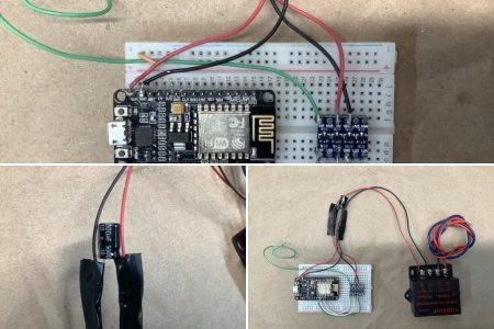
Hello everyone. I am trying to build some arches (using the air seeder hose and conduit as shown in these forums). I am also using hardware I already have
  • Wemos D1 mini ESP8266 devices that will be running WLED
  • 5V 60LEDs/m WS2812B strips
  • 5V60A switch-mode power supply
During testing, I was running WLED on the ESP8266, which was powered by a USB power bank, and powering the LED strip from the 5V pin on the ESP8266, making sure to only run 30 LEDs as recommended by WLED. This works as expected and all looks good.

When I power the LED strip from the 5V60A SMPS, with a common ground between the SMPS and the ESP8266 (still powered from the USB power bank), the LED strip behaves erratically, no matter if it is 30 LEDs or 150 LEDs.
  • the colour order appears to change from the default GBR to BGR
  • LEDs flicker on and off, especially during bright segments
  • the first LED is always on, but in an odd colour
I have seen that you should not power the ESP8266 via the 5V pin, so I will be getting some micro USB plugs and powering it via the USB connector from the same SMPS. But I am concerned about the erratic behaviour when the LED strip is powered from the SMPS.

Does anyone have thoughts or suggestions on this?

Edit: Looking at the WLED wiki, I now realise that I do not have the 470ohm resistor on the data line or the 1000uF capacitor across the 5V and GND lines to the LED strip. Could these be related? I'll have to get some of those components anyway, so hopefully they help.
 
Last edited:

Pavle

Rank updated… 2 season veteran
Joined
Nov 7, 2020
Messages
190
Location
Sydney
I've only looked at WLED briefly last night and from that research, there was definitely a need to have resistors on your data feed so I think that will most likely be the cause.
 

Jorge Bolivar

Full time elf
Joined
Nov 17, 2019
Messages
100
Location
Cleveland, Ohio
Hello, @Steve Williams.
I do start this album to share my past WLED and ESP8266 experiences. Please take a look on how I do wire the project.
1- I will ditch the 470 ohm resistor in favor of a good logic leveler.
2- Keep the 1000uF capacitor. This will save that ESP8266.
3- Run your ESP8266 from the same 5vDC transformer and ditch the USB power bank.
5- On WLED disable the Automatic brightness limiter. This will gave you the LED count control to you and should help with the flickering. BTW 60A should be around 700 led @100% brightness.
6- Be sure you use Unicast on WLED WiFi set up.

if already setup on LED Preferences, Not sure why the RGB order get nverted, are you using any RGB sequencer to output to lights?
Be aware that WLED has a bug related to the pixel 170 not lighting up when in E1.31 mode.

Note:
my project was on 12Vdc. All above should apply equal but just like to be clear.
Good Luck!
 

Steve Williams

New elf
Joined
Feb 17, 2018
Messages
5
Thanks @Jorge Bolivar. Very helpful information there. At the moment I am using WLED's built-in effects, but the plan is to have them controlled via E1.31. I have materials for six arches, each with 150 pixels. I understand the pixel 170 issue due to DMX universes having 512 channels which run out in the middle of that pixel. I likely won't run at 100% brightness, and I may only run four or five arches, so the 60A PSU should be enough to run them. It's my first foray into custom Christmas lighting, so a lot of learning.
 

Steve Williams

New elf
Joined
Feb 17, 2018
Messages
5
@Jorge Bolivar Is that logic level converter boosting the D4 pin from the ESP8266's usual 3.3V up to 5V? I found this guide to NeoPixels on Arduino, and it mentions that pixels powered by 5V need a 5V data line. Is that correct?
 

TerryK

Retired Elf
Joined
Feb 9, 2020
Messages
655
Location
West Central Ohio
I'm not familiar with WLED or the ESP8266. A couple thoughts regarding the WS2812s though. World Semi specs the data levels at 0.3VDD and 0.7VDD. For 5 volt that is 1.5V and 3.5V so Data Line Low should be 1.5 volt or lower and likewise a 3.5 volt or higher for the Data Line High. The spec for VDD is 3.5 volt to 5.3 volt.

Most IC manufacturers (and World semi too likely) will not say their products will fail outside those windows, only that the product may or may not work and if it does it may not have complete functionality. Within the speced windows, the IC will function correctly and if not then it is defective in some manner. Input and supply levels are only 2 or 3 out of many.

Adafruit by the way indicates on their website that Neopixels currently use a SK9812 chip. Typical VDD is 5.2 volt; no min or max listed. Data Line levels are 1.6 and 3.4 at a Vdd=5.0 volt.
 

Steve Williams

New elf
Joined
Feb 17, 2018
Messages
5
@TerryK Thanks for the explanation. I read those in the datasheet for the WS2812B but didn't understand how to interpret them. Now I know.
 

Srmorgan

Full time elf
Joined
Jan 26, 2020
Messages
100
I ran into this same problem. You will need a logic level shifter on the data line unless the data wire is really short. Also the v- will need to go from the psu to light strip and there will also need to be a v- run from the 8266 to the strip as well. The controller needs to measure the difference between the ground and voltage to end out a proper data signal. The v- from the psu cannot be split between the lights and the 8266. It needs to make a triangle. So a v- from the power to the 8266 then out to the lights. I also run between the psu and the lights as a redundancy.
 

Muttley

New elf
Joined
Nov 25, 2020
Messages
10
I set mine up like this. This is one I was just testing because I normally have a fuse on the power in but as it was on the bench I already have a fuse between it and the PSU.

These are 12v pixels controlled by a NodeMCU which can handle the 12v. I have done the same setup on my 5v strips using a D1 mini Pro which likes the 5v and they all seem to be working fine.

This is my first year doing this so I'm applying the KISS principle. If I start to have problems I'll add in the capacitor but so far so good.

20201204_095215.jpg
 
Top