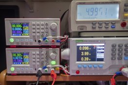
Power Injection testing using multiple PSU's

AussiePhil

Dedicated elf
Administrator
Joined
Jun 20, 2009
Messages
1,606
Location
Canberra, ACT, Australia
Let's get some housekeeping for this thread out of the road first.

Opinions don't count nor does the this is how it's always been done.
Contribute with questions.
Contribute with you own experiments.
Feel free to ask me to test combinations.

do NOT EVER connect two power supplies together at the power supplies to get more current unless they are designed for it and have active load sharing

What I am testing and showing here is passive load sharing.

The first set of tests is fairly basic using seed pixels as they are reasonable low current and suffer from voltage drop at 100%

The following pictures are for 150 seed pixels at 100% driven with white from Vixen and an ECG-12R

The top psu is delivering power to the start of the string via 10A cabling about 1.5M long
The bottom psu is providing the power injection between 100 and 101
Power is feed both ways with Pos/Neg being continuous.
The bench meter is showing the voltage measured between pixels 50 and 51
Power Injection was 1.2M of maybe 22awg, it is thin but approximates the longer length/larger size we use outside.

Single Supply driving 150 pixels peak current around 1.3A
Single supply but with shared ground at pixel 100 peak current nearly 1.7A but pixels still went red due to v drop.
Dual supplies as per photos

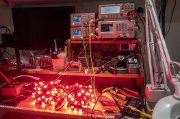
test setup, the 3 bright bits are 50 seed pixels 100% white,
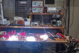
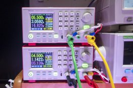
PB200285.jpg

All the initial tests done with both supplies set for 5V
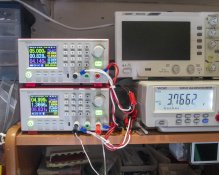
PB200287.jpg

so here we see that PSU1 is providing 828mA to the start of the string with 3.76V being the voltage at pixel 50-51 when also getting power from pixel100-101
PSU2 is providing 1.366A center feeding at least 100 pixels

Now the constant talking point.... the supplies must be matched ..... this photo calls that busted... but we have more testing to do.
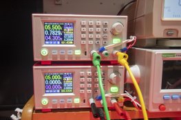
I deliberately set PSU2 that is doing the PI to 4.8v
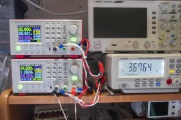
PB200286.jpg

Net effect was an extra 70mA from PSU1 with the corresponding drop in current from PSU2 at the PI source.
Also there is a little extra voltage drop evident.

Honestly it was what i expected to see.

I have some normal 2811 pixels coming in very soon and will retest with them and thicker PI wiring.

For red/green/blue the max currents were lower hence the voltage drops where lower as well but the current split up remains constant

One thing for consideration is that center feed power is better generally than end feed.

One thing i would like to do is fire up the scope and look how the data stream looks at each point.

Cheers
Phil
 

welby

New elf
Joined
Feb 6, 2020
Messages
25
Location
Newcastle
I've been curious as to why people never connect positives as i could never see the problem in doing it. In my opinion it's no different than two batteries in parallel.
 

Notenoughlights

400,000+ twinkly lights
Joined
Oct 16, 2016
Messages
654
Location
Christchurch, New Zealand
I've been curious as to why people never connect positives as i could never see the problem in doing it. In my opinion it's no different than two batteries in parallel.
Slight differences in voltages will cause power supplies that are not designed to be paralleled up to fight as they try to match the voltage they have been set at, put simply. This is done usually using a special data link between two supplies, i.e server power supplies, high end meanwells etc. Batteries can also be damaged by connecting two that are at different voltage levels as one tries to charge the other and sometimes at ultra high currents causing damage/fire, which is why Li-Ion batteries are matched to tight tolerances when connecting them in parallel
 

AussiePhil

Dedicated elf
Administrator
Joined
Jun 20, 2009
Messages
1,606
Location
Canberra, ACT, Australia
Slight differences in voltages will cause power supplies that are not designed to be paralleled up to fight as they try to match the voltage they have been set at, put simply. This is done usually using a special data link between two supplies, i.e server power supplies, high end meanwells etc. Batteries can also be damaged by connecting two that are at different voltage levels as one tries to charge the other and sometimes at ultra high currents causing damage/fire, which is why Li-Ion batteries are matched to tight tolerances when connecting them in parallel
Said in my very first post......
do NOT EVER connect two power supplies together at the power supplies to get more current unless they are designed for it and have active load sharing
This thread is not about connecting two or more supplies together at the supply but using passive load sharing correctly and already clearly shows you can use two supplies to share load even when they are not matched.
 

AussiePhil

Dedicated elf
Administrator
Joined
Jun 20, 2009
Messages
1,606
Location
Canberra, ACT, Australia
I've been curious as to why people never connect positives as i could never see the problem in doing it. In my opinion it's no different than two batteries in parallel.
As notenoughlights said above it's not the same two batteries but connecting the positives along the string when power injecting is passive current sharing is quite valid, doesn't need exactly matched supplies but they definitely should be closer then the 0.2v differential i tested above.
Two batteries can be connected in parallel as long as they also are similar voltages at the time of connection.
Lead acid and SLA are connected exactly like this in every telephone exchange that has more than one bank of batteries.

Ideally in a passive current share arrangement with dumb power supplies you would also run oring diodes to block reverse feeds and I will look further at that once i get some in.
Modern SMPS units when directly connected together at the units without or-ing diodes can fight each other hence the big bold don't do it warning
Cheers
Phil
 

TerryK

Retired Elf
Joined
Feb 9, 2020
Messages
655
Location
West Central Ohio
Supply currents shown are not what I would expect. I would think a fairly close 2 to 1 amperage ratio as supply 1 is powering the first 50 pixels and supply 2 powers approximately pixel 51 to the end. Could it be voltage drops seen but not considered at pixel 1 compared to pixels 100/101 (close to the pixel, not distanced a meter or 2 by the power injection wiring)? Also, what is the accuracy of the supply displays, voltage and digit resolution/rounding?

Likely to not very relevant to what you attempting to prove, but have you considered the current division location in a string powered at 2 points? That is, for your 150 pixel string, pixel 50/51 would be the expected low point if voltage at pixels 1 and 100/101 are nearly the same but the amperage division point should shift upwards if the voltage drops at pixels 100/101.

Also needing considered with load sharing is how the supplies handle overload. For example, Meanwell's "Hiccup" mode or the entering of current limiting.
 
Last edited:

AussiePhil

Dedicated elf
Administrator
Joined
Jun 20, 2009
Messages
1,606
Location
Canberra, ACT, Australia
Supply currents shown are not what I would expect. I would think a fairly close 2 to 1 amperage ratio as supply 1 is powering the first 50 pixels and supply 2 powers approximately pixel 51 to the end. Could it be voltage drops seen but not considered at pixel 1 compared to pixels 100/101 (close to the pixel, not distanced a meter or 2 by the power injection wiring)? Also, what is the accuracy of the supply displays, voltage and digit resolution/rounding?
Thanks Terry,
When you have passive load sharing rather than fully isolated Power inject the measured current will not be a clean ration based purely on pixel counts, hence the practical tests.
PSU1 feeds pixel 1 to 50+
PSU2 center feeds 100 -> 50 or less and 100 ->150
There is an addition ground return path for PSU1 via pixel 100/101 ->psu2->psu1 as these are not isolated in relation to earth, this is not unusual but changes the expected current share ratios a little.
There is voltage drop on both the feed in power cable and the PI cable but this initial baselining was to see the view from the PSU outputs and how they supplied current both at matched voltage and at mis-matched voltage.

In checking the outputs with the 80,000 count bench and two portable meters they all agreed to a few mV which is about expected... i don't have calibrated test gear but at least for this accuracy past even 1/100th of a volt and amp would be redundant.

Likely to very relevant to what you attempting to prove, but have you considered the current division location in a string powered at 2 points? That is, for your 150 pixel string, pixel 50/51 would be the expected low point if voltage at pixels 1 and 100/101 are nearly the same but the amperage division point should shift upwards if the voltage drops at pixels 100/101.
Actually as these are constant current driven led's, the divison point will move up and down the string as the voltage drops change along the string due to essentially wire resistant/voltage/current draw.... already the second ground return loop changes the point itself. which in reading what you wrote and I wrote seem to agree.
This is how we exploit the passive current sharing effectively without needing to isolate sections of pixels
Also needing considered with load sharing is how the supplies handle overload. For example, Meanwell's "Hiccup" mode or the entering of current limiting.
I'll withhold my comments till i have on hand an electronic load to simulate short circuits fairly safely. obeying my own rules at the top of the thread :) let me test, think it will be illuminating :)
Cheers
Phil
 

TerryK

Retired Elf
Joined
Feb 9, 2020
Messages
655
Location
West Central Ohio
Agree with pretty much everything except the current division. You mentioned all pixels at 100% white and PS1 connected to pixel #1 and PS2 connected to pixels 100/101. Also indicated were positives and negatives connected through so voltage drops in the positives and voltage rises in the negatives should be consistent across the structure.

In your reply you mention a second ground loop. Is there a negative connection causing the current imbalance which is not obvious? A wiring diagram may help. As an aside, I corrected a minor typo in my first post (#7).
 

AussiePhil

Dedicated elf
Administrator
Joined
Jun 20, 2009
Messages
1,606
Location
Canberra, ACT, Australia
Agree with pretty much everything except the current division. You mentioned all pixels at 100% white and PS1 connected to pixel #1 and PS2 connected to pixels 100/101. Also indicated were positives and negatives connected through so voltage drops in the positives and voltage rises in the negatives should be consistent across the structure.
Actually in thinking about that, the voltage drop along say 15M of string (150 pixels) will decrease the further away from the power input as each 100mm draws less total current from the supply... we are dealing with series resistance for the wire along the length and constant current for each equivalent parrallel load (the pixel)
The the input sees all the current with the current dropping per section by the value of the CC led till at the end the last 100mm only has to account for say 5.6mA on red
The last lot of measurements shows this in 50 pixel sections

In your reply you mention a second ground loop. Is there a negative connection causing the current imbalance which is not obvious? A wiring diagram may help. As an aside, I corrected a minor typo in my first post (#7).
Yeah - must have been mistaken on seeing it as i can't replicate it

------------------
Ok here's tonight's data
The voltages are measured at 0 - 50 -100 - 150
I1 = current supplied to the start of the string
I2 = current supplied when injected between 100/101 or after 150

V inV - 50v-100v-150I1I2
Red
end 5v4.933.62.852.61740-
PI -1004.984.694.974.67280520
PI-1504.974.44.394.97410385
Green
end 5v4.943.6832.8730-
PI -1004.984.684.974.64285528
PI-1504.974.384.364.97410387
White
end 5v4.942.952.322.181250-
PI -1004.944.134.934.137501450
PI-1504.93.293.34.9410901070

It would seem that PI at 100 and at 150 achieve the same result here but with different currents supplied from the supplies

Bonus test - short circuit after 150 with all white
single end feed no short
V in - 4.89
I1 - 1230 mA
Shorted at 150
V in - 4.88
I1 - 1375 mA
v-100 was 1.29v
Current was voltage drop limited along the length

I repeated that with PI at 100 and got 3A being drawn with the short 50pixels away and the string was actually getting hot...... in no way though would a fuse have been blown that we normally use

Cheers
Phil
 

AussiePhil

Dedicated elf
Administrator
Joined
Jun 20, 2009
Messages
1,606
Location
Canberra, ACT, Australia
Moving onto some fresh, hot of the plane 2811 square pixels from Ray with chinese 18AWG wiring.

picture of the test set with two 50 pixel strings running
In the picture power is being feed from both ends, voltage is measured at the inject point for both ends, V and Current are measured on the supplies
PB250313.jpg

Test setup is Data and power go in to pixel 1 from the bottom supply, these pixels are CC driven leds, the values are in the table below, Power inject is down at the other end for the PI test and current is equally shared.
I did only test against red and white for dual power

2811 square pixelsVpsuVinV50!1
50 unit string
Red
5.1​
5.05​
4.6​
0.86​
17​
Green
5.1​
5.05​
4.6​
0.86​
17​
Blue
5.1​
5.05​
4.6​
0.86​
17​
White
5.1​
4.98​
3.85​
2.18​
I@5.5v = 2.34
43​
100 string
Red
5.1​
5​
3.45​
1.57​
15.7​
Green
5.1​
5.01​
3.74​
1.37​
15.7​
Blue
5.1​
5.01​
3.73​
1.38​
15.7​
White
5.1​
4.94​
2.83​
2.67​
Dual Power
Red
0.84​
0.85​
1.69​
16.9mA
White
2.14​
2.2​
4.34​
43.4mA


Some Photos
This one is setting the supplies 1v apart very drastic, this was 100% white and shows current sharing is still working
PB250315.jpg

Switching to 100% red @ 0.5v difference current was only being supplied by one supply at around 0.3v difference current was again being shared
PB250316.jpg

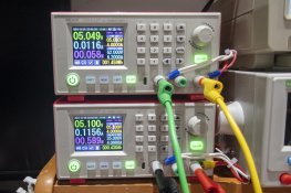
Next we shifted to 6% red, this forced the supplies to be more closely matched for the passive load sharing to function correctly
We are down to 50mV difference
PB250318.jpg

Any 3.5 digit multimeter could match even the cheap 350W units this close

TLDR, scrolled to the bottom.... 100 pixels = 4.3A with no more than 50 pixels from a power injection.
No wires were cut or harmed in this testing

Cheers
Phil
 

AussiePhil

Dedicated elf
Administrator
Joined
Jun 20, 2009
Messages
1,606
Location
Canberra, ACT, Australia
On top of the above i wondered what the effect would be of having a short circuit just after pixel 50.
So to do that i went back to a string of 50 and hooked the out end up power wise to the electronic dummy load

I'll give you the short version ..... no fuse would have been blown, actually nothing seemed to get hot and max current requested never peaked due to overall voltage drop on the string
PB250321.jpg
The supply was being allowed up to 6A - the load was set to draw 5A
Input to the string was 5v
pixels dropped out around 25 into the string going red fast then nothing
Current was 4.83A from the supply

I do have some older pixels i'm prepared to sacrifice to test where a short was to occur enough current would flow to pop a fuse but not tonight.

Cheers
Phil
 
Top