Navigation
Install the app
How to install the app on iOS
Follow along with the video below to see how to install our site as a web app on your home screen.
Note: This feature may not be available in some browsers.
More options
-
2026 Mini Christmas Light Expos - RSVP Now
Perth Mini: 13 June | Melbourne Mini: 4 July | Sydney Mini: 4-5 July | Brisbane Mini: 26 July -

You are using an out of date browser. It may not display this or other websites correctly.
You should upgrade or use an alternative browser.
You should upgrade or use an alternative browser.
Power supply to smart receiver
- Thread starter Jon_101
- Start date

bpratt
Senior elf
short answer, yes. ")
- Thread starter
- #3
Thanx, short answer is goodshort answer, yes.
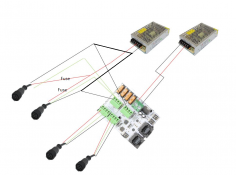
The safest answer is no if you're powering pixels through the pigtails on the left. The on-board fuses are (usually on most controllers) on the positive. For the left-hand power supply, you have bypassed the fuses but the current still flows through the negative trace on the controller in order to complete the circuit.
Last edited:
- Thread starter
- #6
Thanks for your answer, but even if you connect ground after the fuse,The safest answer is no if you're powering pixels through the pigtails on the left. The on-board fuses are (usually on most controllers) on the positive. For the left-hand power supply, you have bypassed the fuses but the current still flows through the negative trace on the controller in order to complete the circuit.
I should explain how to do this correctly. Connect the negative output of the left-hand power supply to the controller's outputs instead of its input. Add a fuse in each positive wire between the pigtails and the left-hand power supply.
I should explain how to do this correctly. Connect the negative output of the left-hand power supply to the controller's outputs instead of its input. Add a fuse in each positive wire between the pigtails and the left-hand powe
Thanks, I did it your way and its working.I should explain how to do this correctly. Connect the negative output of the left-hand power supply to the controller's outputs instead of its input. Add a fuse in each positive wire between the pigtails and the left-hand power supply.
TerryK
Retired Elf
The lack of a detail or two prevents a precise answer. Specifically, what is the amperage ability of each supply? What is the amperage demand for each pixel string; at your intended or configured drive level (white)? And a note that if one takes your sketch as it is literally drawn, the placement of the wire splices add ambiguity.
To answer your question without suggestions based on assumptions, I agree with 'bpratt', yes.
To answer your question without suggestions based on assumptions, I agree with 'bpratt', yes.