Using lever nuts to connect more than one device to a power supply terminal

janastas

Full time elf
Joined
Nov 30, 2020
Messages
120
Morning all,

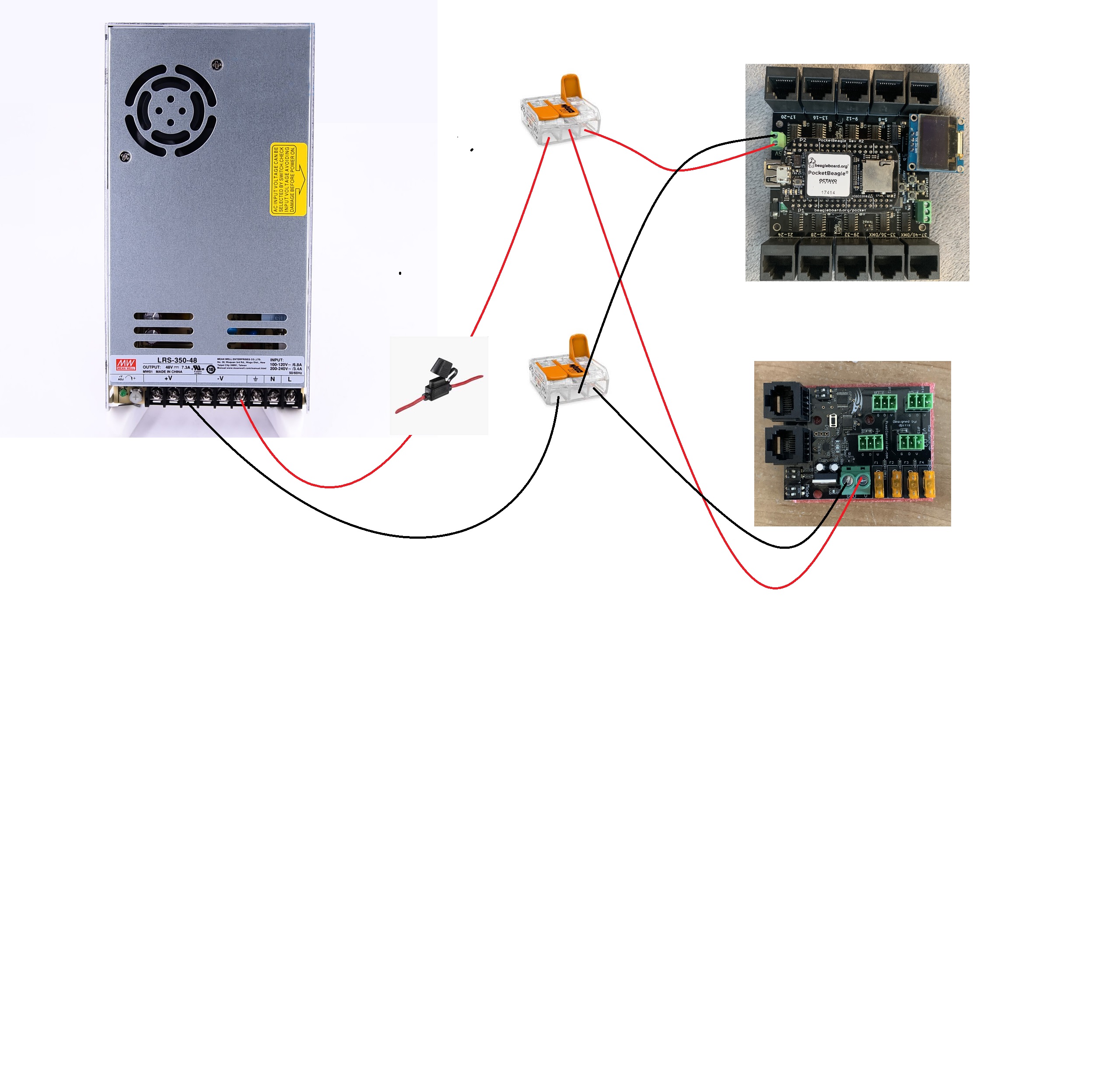
I just wanted to confirm the following wiriring won't cause me any issues.

The long story short is I have an LRS-350-5v dc power supply where I'm already utilising the other two positive / negative terminals for other devices and I only have one positive / negative terminal left.

I want to hookup two devices (Kulp K40 board and also a falcon differential receiver) to this terminal and wanted to use wago lever nuts to do this.

See the diagram below, just wanted to check what I'm doing is correct.

Pretty much there will be one cable coming out of the positive terminal with an inline fuse to the first wago lever nut, then one wire going to the K40 and the other one to the differential receiver.

Same thing for the negative terminal but no line fuse going to the second wago lever nut, then out ot each devices negative terminal.


Elecgreg

New elf
Joined
Dec 11, 2020
Messages
28
Location
The Rock
It may work OK however consider what the other TWO devices you have connected and the power draw on the PSU as that is the limiting factor to the connection of devices given that the differential receiver will be controlling pixels the quantity of pixels may along with all other power being drawn from the supply my cause you problems.
 

janastas

Full time elf
Joined
Nov 30, 2020
Messages
120
that will work fine.

but you know there is multiple output terminals on the power supply right?

The other two terminals are already being used hence why I wanted to conenct these two devices to the single terminal.
 

janastas

Full time elf
Joined
Nov 30, 2020
Messages
120
It may work OK however consider what the other TWO devices you have connected and the power draw on the PSU as that is the limiting factor to the connection of devices given that the differential receiver will be controlling pixels the quantity of pixels may along with all other power being drawn from the supply my cause you problems.

The power supply is one from Hanson Electronics (A Scott SC-400-5-70 so 350W 70A output)

Assuming that the Kulp K40 shouldn't draw too much current (Not sure what the max would be) but the pixels connected ot the diffrential receiver will obviously have a certain amount of draw.

If I just use the 4 ports from the diff receiver to also power the pixels I'd be looking at 4 x 5A = 20A which is well below the 70A output.

I'll also have a power 8 distro board which can handle around 1000 pixels @ 100% brightness that can draw up to 60A but my plan is to only run at 30% brightness.

Not sure how many pixels will be running of this controller as yet. Just wanted to make sure I had the wiring right for the K40 and the diff receiver before I start running cals for how many pixels.
 

janastas

Full time elf
Joined
Nov 30, 2020
Messages
120
have you considered using something like a hexfuse? http://www.hansonelectronics.com.au/product/hexfuse2/

This is my current setup, there's a power 8 distro board for power injection on the bottom level with the K40 and diff receiver on the top level.

I just want hte K40 and diff receiver coming off the power supply instead of using the outputs from the distro board.


LawrenceDriveLights

Senior elf
Joined
Jan 16, 2018
Messages
582
Sorry to hijack thread, noticed the PSU mounts. Just note these designed for the thin Meanwell PSU’s and if u stack two of the generic Chinese ones using these you many not have enough ventilation for the fans. Just check to ensure the gap between the stacked PSU’s is sufficient to allow adequate air flow
 

TerryK

Retired Elf
Joined
Feb 9, 2020
Messages
655
Location
West Central Ohio
Nothing really wrong with the wiring in your posted graphic. With the single fuse one does need to evaluate what may happen if 1 of the 2 devices 'hogs' all of the available current. It would likely be better I think to have each device individually fused.
Cage clamp terminals which the Wago Lever terminals are also should not be used with wire ferrules. They also need to be properly sized to the current demands one intends to drive through them.
 

janastas

Full time elf
Joined
Nov 30, 2020
Messages
120
Sorry to hijack thread, noticed the PSU mounts. Just note these designed for the thin Meanwell PSU’s and if u stack two of the generic Chinese ones using these you many not have enough ventilation for the fans. Just check to ensure the gap between the stacked PSU’s is sufficient to allow adequate air flow

Yep gotcha, i have some low profile psu's on the way from China next month so just wanted to set this one up to drill the holes and will install two low profile in this box and move the generic chinese one to a cg-1500 box.
 

janastas

Full time elf
Joined
Nov 30, 2020
Messages
120
Nothing really wrong with the wiring in your posted graphic. With the single fuse one does need to evaluate what may happen if 1 of the 2 devices 'hogs' all of the available current. It would likely be better I think to have each device individually fused.
OK thanks, so pretty much one wire in to the wago lever termine then two out each with a fuse.

Cage clamp terminals which the Wago Lever terminals are also should not be used with wire ferrules. They also need to be properly sized to the current demands one intends to drive through them.
The plan was to just strip the wire and feed straight into the level terminal without a wire ferrule.
I think the wago's can handle up to about 30A but for the K40 and the diff receiver I don't think the current demand would be that high?
 

BAZMick

Full time elf
Generous elf
Joined
Nov 26, 2019
Messages
484
Double check your wiring from the PSU just to be safe, in the graphic of the OP you have the red+ wire connected to the negative on the PSU, and vice versa for the neg- wire.
 

janastas

Full time elf
Joined
Nov 30, 2020
Messages
120
Double check your wiring from the PSU just to be safe, in the graphic of the OP you have the red+ wire connected to the negative on the PSU, and vice versa for the neg- wire.

yep sorry wsa just me putting togething a bad diagram but the wiring on the physical hardware is fine and has been double checked.
 
This thread is very old. An answer might not be needed anymore.
Top