Why is there a 300 ohm resistor in series with the data line?

Greg.Ca

Apprentice elf
Joined
Jan 1, 2013
Messages
92
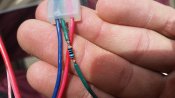
Check the attached photo first. This 300 ohm resistor has been causing nothing but havoc. This resistor came from Ray's factory in China with this mysterious heat shrinked 'bump' attached and soldered in series with the data in 'green' wire. As it turns out, this mysterious 300 ohm resistor causes the strip not to light up directly from my P12S . When this resistor is removed (bypassed) from the data in connector, the strip functions correctly.

I have no idea as to why Ray's Chinese workers would solder in a 300 ohm resistor directly in line with the data input connector on my strip. What function does it supposed to perform?

These strips are 5V WS 2812b's with 150 pixels per strip. Any clue as to why that resistor is soldered in place will perhaps help me determine as to why some of my strips are intermittently not working. The common demonenator as to intermittant defective strips seems to be this pesky 300 ohm resistor that is in series with the data in of the strip. ARGHHHHH!!!!!!!

I ordered 60 these strips from Ray and have a 20% failure rate that seems to be directly related to this resistor. At least 50 of these 60 strips are working somewhat but I need to know what this resistor's function is.

Thanks --Greg--

Any comments??
 

Attachments

  • 20141130_110801.jpg
    20141130_110801.jpg
    806.2 KB · Views: 48

AAH

I love blinky lights :)
Community project designer
Joined
Dec 27, 2010
Messages
4,188
Location
Eaglehawk
By design the 2811 and 2812 and possibly other pixels are designed to have a 30 (not 300) ohm resistor in series with them. This is to match impedances of the cable. If you happen to be driving the strips from J1Sys boards your problems are likely to be exacerbated as for some reason the P2 at least and I expect others have a 300ohm in series with the outputs rather than 30 ohm. As to why there's a 300ohm wired in externally I can only guess they have the wrong value and also the strip didn't come with input resistors designed in.
 

fasteddy

I have C.L.A.P
Global moderator
Joined
Apr 26, 2010
Messages
6,648
Location
Albion Park NSW
I would dare say it is used to reduce the amount of failures of the 2812b chip when people plug them in with power on as these are known to fail the first pixel when plugged in and out when running.
But this will most probably shorten the distance the lighting works from the controller
 

multicast

Senior elf
Joined
Jul 13, 2013
Messages
715
Theres two reasons why resistors are commonly put on data lines.
[/color]
[/color](1) The 'data' line is actually a signal transmission line. For signal integrity, any mismatch in impedance of the transmission line formed by a pcb trace connectors, cable and attached components can cause reflections of signal transitions. If these are allowed to bounce back and forth along the path reflecting off the mismatches at the end for many cycles until they die out, the signals "ring" and may be misinterpreted either by level or as additional edge transitions.
[/color] Typically an output pin has a lower impedance than the trace and an input pin a higher impedance. If you put a series resistor of value matching the transmission line impedance on the output pin, this will instantaneously form a voltage divider and the voltage of the wavefront traveling down the line will be half the output voltage. At the receiving end, the higher impedance of the input essentially looks like an open circuit, which will produce an in-phase reflection doubling the instantaneous voltage back to the original. But if this reflection is allowed to reach back to the low-impedance output of the driver it would reflect out of phase and constructively interfere, subtracting again and producing ringing. Instead it is absorbed by the series resistor at the driver which is selected to match the line impedance. Such source termination works pretty well in point-to-point connections.
[/color]Current limiting in lazy level translation is another common reason. CMOS IC technologies of different generations have different optimal operating voltages, and may have damage limits set by the tiny physical size of the transistors. Additionally, they cannot natively tolerate having an input at a higher voltage than their supply. So most chips are built with tiny diodes from the inputs to the supply to protect against overvoltage. If driving a 3.3v part from a 5v one (or more likely today, driving a 1.2 or 1.8 v one from a 3.3v source) it's tempting to just rely on those diodes to clamp the signal voltage to a safe range. However, they often cannot handle all the current that can potentially be sourced by the higher voltage output, so a series resistor is used to limit the current through the diode.
 
Top