When we first introduced our xCG-x2 series (ECG-D2, ECG-P2, DCG-P2) of controllers we planned for and promised a set of expansion boards to follow. Our initial design of an expander never made it past the prototype stage. One was shown at several Aussie Mini’s in 2012.
We’ve spent the last month working on a new ASIC (Application Specific IC) solution to our continuing need for more powerful and higher count pixel outputs. The first application of this new solution is our long awaited XCG-X2A.
The XCG-X2A is out of the prototype stage and is in final pre-production right now and we expect an initial production run to be complete by the first week of April 2013.
The XCG-X2A is a small board that mates to the riser connectors on the xCG-x2 series controllers. The combined boards will still fit in the extruded aluminum case with a set of new end panels.
The XCG-X2A includes:
· Real Time Clock w/battery (RTC)
· microSD socket
· 4x option switches
· 4x status LEDs
· 3x 3Pin Flexi-Port I/O connectors
The RTC will be used for scheduling stand-alone sequences designed using our Compiled Object Oriented Lighting (COOL) language.
The microSD will be used to store and retrieve pre-programmed sequences. It is NOT our intention to record raw captured sequences directly to the microSD. The sequences must be preprocessed by application software on your PC to create compatible COOL sequences. Simple COOL sequences can be written directly in XML.
The 4x option switches and 4x LEDs will be used to control the operation and display status information under software control.
The power and flexibility of the new expander is in the Flexi-Ports. All three ports offer identical hardware and software options as described below. Each connector has three pins labeled: G, C, D which match the signals Ground, Clock, Data used by one of the modes. Please note that the 3Pin signals are the same signals as pins 1-3 of our standard GCDV 4Pin pixel connector. We have removed the ‘V’ pin for two reasons: we wanted to squeeze 3x connectors across the same 42mm space and most xCG-x2 installations far exceed the nominal power capabilities of the board. For power distribution options the user should consider the ECG-P12 series.
The G pin is permanently connected to the signal ground/common on the board.
The C and D pins can be hardware configured in three modes: +5V, Buffered Output, Unbuffered Input/Output. The Unbuffered Input/Output includes optional pull-up resistors.
Subject to hardware configuration jumpers the software can implement several different operating mode on each Flexi-Port:
· GCD – Gnd, Clk, Dat for a single 4Wire or 3Wire pixel output
· GC – 3Wire pixel output, GD – 3Wire pixel output (two strings on ONE connector)
· GCD – two unbuffered digital inputs (CD) for switches or external triggers
· GCD – one unbuffered digital input (C or D) with 5V supplied on the other C/D pin
· GCD – two unbuffered digital outputs (CD) to control external devices
· GCD – one unbuffered digital output (C or D) with 5V supplied on the other C/D pin
· GCD – one unbuffered digital input (C), one unbuffered output (D)
· GCD – I2C interface for external devices
· GCD – 1-Wire interface (C) with 5V (D) for external devices
The optional pull-up resistors are different on each connector to allow flexible choice for I2C or other uses:
· P3C/P3D – 1.8K
· P4C/P4D – 4.7K
· P5C/P5D – 10K
Please don’t let all these options scare you. In the most common mode the user will leave the jumpers as set when shipped and select either: 1x 4Wire/3Wire per connector or 2x 3Wire per connector under software control for each connector.
Pricing not yet determined. Initial software releases will support the same pixel types we currently support and NOT include any of the RTC and microSD COOL programming. So it will just be a flexible 3-6 string add-on board. We are working on adding GECE support and other pixel types and will be adding simple COOL capability ASAP.
Please see the photos below:
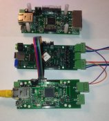
· X2A_1 – the prototype board
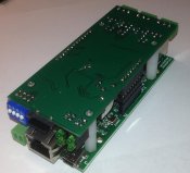
· X2A_2 – front to back: ECG-P2, XCG-X2A, ECG-D2. The ECG-P2 and XCG-X2A are tethered together for bench testing. The ECG-D2 has the stand-offs and riser pins installed to mate to the XCG-X2A
· X2A_3 – rear of mated ECG-D2/XCG-X2A
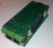
· X2A_4 – front of mated ECG-D2/XCG-X2A
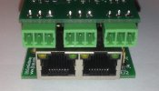
· X2A_5 – close-up front of mated ECG-D2/XCG-X2A
-Ed


