Power Injection Sanity Check - 47" Ice Princess

Pavle

Rank updated… 2 season veteran
Joined
Nov 7, 2020
Messages
190
Location
Sydney
I already see that Pavle (original poster) understands this concept but there should rarely be a reason to cut the positive wire in the pixels next to an injection point. This would result in a cumbersome configuration because it doubles the number of injection points required in order to get all pixels within a certain minimum distance from an injection point. Power can travel in both directions from an injection point. It would be better to cut the positive halfway between the injection points.

I am still in the partially understands phase, still a way to go yet. For me, the more viewpoints offered, the more I question my configuration, however without all of the contributions nothing would be gained so very helpful to get all opinions.

The cutting of V+ is still a little foreign to me and even in this thread we have different opinions on this. I understand the logic, but still playing around with the practical implementation.

Will attempt to put together a diagram for this example and seek some additional advice.
 

TerryK

Retired Elf
Joined
Feb 9, 2020
Messages
655
Location
West Central Ohio
Not entirely. You also have to remember fusing, you shouldn't run cable to a prop with 500 pixels fused for 5amp and then inject further into the prop at say 100, 300, 300 etc for 5v and then fuse that power injection. Best practice ...
I actually do this or something similar and have no problems. Yes, I agree one needs to remember fusing. I fuse each injection point at 5 Amp. Thus defining the number of pixels powered by the injection point at my chosen drive level (presently a maximum of 70/80%). Whatever the number of pixels are, half are driven towards the beginning of the string and half towards the end from the middle power injection points.

For example: lets say at the chosen drive level I can drive 90 pixels without discoloration. However, to not break the V+ means powering 180 pixels at a middle injection point (assuming equal pixel drive, half the current towards the beginning and half towards the end. But 180 pixels at the chosen drive level is greater than 5 Amp. I 'reverse' calculate and determine the number of pixels I can power equal or less to 5 Amp. Let's say that is 80 pixels.
Without breaking the V+, that means injection point #1 will be Pixel #1 and since it is driving only 40 pixels its current will be less (half, probably about 2.5 Amp) of any of the other middle injection points (and by calculation those should be near 5 Amp). Injection point #2 will be between Pixels #80 and #81. Injection point #3 will be another 80 down the string at Pixel #160.

Becomes rather obvious a several hundred pixel prop has multiple power injection cables ran to it. I power mine with 1. How? By running a 15 Amp power injection cable to the prop and pealing off 5 Amp 'daughter' cables to the injection points. Each 'daughter' cable is fused at 5 Amp. The primary cable is fused at 15 Amp at its beginning.
 
Last edited:

TerryK

Retired Elf
Joined
Feb 9, 2020
Messages
655
Location
West Central Ohio
Thank you for this information. I suppose it assumes only one power supply. I tried to find contact information for the site but there appears to be none.
When V+ is broken this is due to another power supply being added. You could treat each new power supply section separately as it does not affect any other section. The pixel count would start again from 1 on the graph but could be renumbered when printed out. The graphs for the different sections could then be connected to give the whole picture. I found the post you referenced and that is what they did. However, there appears to be no way to not start at pixel 0 for the first point.
Without discussing the calculator design considerations with its author, my assumption is the purpose of the calculator is only to show voltage drop within a string and determine best placement for power injection points. As such, multiple power supplies was likely not considered although he/she may not have wanted to open that 'can-of-worms'.

Depending upon design/configuration, adding a power supply does not mean requiring one to break the V+ (probably going to catch some flack with that). Some supplies are meant to be paralleled and there are several methods to parallel supplies that are not designed to do so. And some supplies by design just cannot be paralleled or should not be. For example, trying to parallel a pair of Meanwell LRS-350-5 supplies is asking for trouble. Using a pair of RSP-320-5 supplies done properly should be possible. Why? The method they use to handle an overload.

Another scenario is the use of separate supplies not paralleled where the V+ is not broken. While if done carefully I think this is possible, I would suggest it is not for those 'faint-of-heart' and as such my recommendation is don't even think about it.

Edit a day later: This assumes the V- of the supplies is connected. To briefly explain, any output difference between supplies is forced into the string where their V+s connect. If both outputs are close (in voltage) then it would not be much of a problem but on an overload or supply shutdown high string amperage might result.
To sum: I suggest breaking the V+ when using muliple power supplies unless one is using multiple supplies intended to be paralleled by design such as a Meanwell RSP-1000-12 or similar. And of course paralleling them at the supplies.
 
Last edited:

Pavle

Rank updated… 2 season veteran
Joined
Nov 7, 2020
Messages
190
Location
Sydney
a several hundred prop has multiple power injection cables ran to it. I power mine with 1.
From the xEssentials video I linked in the OP, Bill Porter has used a similar method, without the 'daughter' fusing see attached examples grabbed from the video:

ExampleA.JPG

ExampleB.JPG

ExampleC.JPG

My interpretation of this method is load balancing.

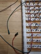
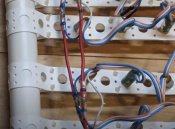
Currently, I have setup my 550 prop without the V+ being cut, however I have 2 circuits with the 1st being node 1 to node 400, where I've picked up power injection points at node 1, node 101, node 201, node 301 and node 400 - For Node 1, the cable comes from the controller and it carries data, V+ and V-
I've then got another cable (14AWG) that runs from the same power supply with separate fusing and it carries V+ and V- and runs to node 101, 201, 301 and 400

The 2nd circuit has a cable comes from the controller and it carries data, V+ and V- and is connected to node 401, I've then got another cable (14AWG) that runs from the same power supply with separate fusing and it carries V+ and V- and runs to node 501 and 550 - again I've not cut any V+

Now, this setup is working, it has run very successfully during testing (about 6 hours run time), but it may not be theoretically correct - is that right?

If I was to 'correct' this and start to cut V+ wires, where would you make these cuts?

:unsure:
 

pixelated

New elf
Joined
Mar 18, 2021
Messages
19
Location
Canada
If you connect several power supplies with V+ not broken, aren't they connected in parallel? I must be missing something.

There are Meanwell power supplies that are designed for current sharing and some that are not. I doubt that most of the cheaper power supplies offer the current sharing option. I have tried to research methods of paralleling power supplies. I guess you can set the voltage of the supplies when at load to be as close to each other as possible and hope for the best. The best option appears to be the use of ideal diode modules. With these it appears that you can parallel multiple power supplies. How do you do it? Thank you.
 

i13

Dedicated elf
Joined
Jul 5, 2013
Messages
1,172
Pavle, If you're going to cut the positive wire in the pixels, do it halfway between each injection point. Assuming that you have one fuse per injection point, this stops the fuses from sharing the load if there is a short. This is really only a small detail; the thing that matters most is that it is working. If you have a single fuse on a branching wire so that multiple injection points share the same fuse then I see no need to cut the positive. I similarly see no need to cut the positive if you've fused the negative. The ability to cut the positive between injection points is the reason that I suggest fusing the positive, not the negative.

pixelated is correct that if multiple power supplies are connected in parallel through the string of pixels in that scenario. I see no need to have power supplies connected in parallel; just cut the positive wire in the pixels halfway between each power supply.
 

Pavle

Rank updated… 2 season veteran
Joined
Nov 7, 2020
Messages
190
Location
Sydney
Pavle, If you're going to cut the positive wire in the pixels, do it halfway between each injection point.

thanks for your assistance.

I think all that is required on this prop to comply would be if I were to cut the positive wire between node 50 and 51 - this would give me 50 nodes running from a port of my controller with the remainder of this string getting power from my single fused 14AWG wire that is tied to nodes 101, 201, 301 and 400 for a total of 349 nodes with no more than 50 nodes to each power injection point.

The second string is node 401 to 550 and has power coming in from the controller at node 401, then power injection at 501 and again at 550.

I believe I did misrepresent the xEssentials video by overlooking the rule about keeping fused zones separate and I believe that is what you are also explaining @i13

Does that sound correct?

also, just to reaffirm, I’m only using one power supply in all of the above considerations and my fused power injection is from a falcon fused distro board
 

TerryK

Retired Elf
Joined
Feb 9, 2020
Messages
655
Location
West Central Ohio
If you connect several power supplies with V+ not broken, aren't they connected in parallel? I must be missing something.

There are Meanwell power supplies that are designed for current sharing and some that are not. I doubt that most of the cheaper power supplies offer the current sharing option. I have tried to research methods of paralleling power supplies. I guess you can set the voltage of the supplies when at load to be as close to each other as possible and hope for the best. The best option appears to be the use of ideal diode modules. With these it appears that you can parallel multiple power supplies. How do you do it? Thank you.
I edited my post above to correct it a bit and make it more understandable.

Multiple supplies with the V+ not broken would indeed parallel them via the string V+. This method could have problems depending upon how 'matched' the supplies are, that is they will I think try to equalize through the string connections.

Also correct, Meanwell and other manufacturers have supplies intended for parallel operation and typically those supplies are higher end supplies. The additional engineering/components/build costs rule out the possibility of parallel capable supplies being low in cost.

Regarding how to parallel supplies without designed in parallel capability, the method I am most familiar with (and the most common I think) is the use of diodes to prevent current reversal. This also is coupled with careful adjustments of the supply to balance supply load. High amperage ideal diodes are a bit rare I think; do not recall seeing any or any designs for them actually. I've seen a low ohm series resistor design too which is rather crude and does not regulate well.
Paralleling supplies this way is pretty much an act of desperation in my opinion. I know it's possible but to avoid the headaches I'd up-size the supply or use parallel capable supplies from the start (which I'm already planning).
 
Last edited:

TerryK

Retired Elf
Joined
Feb 9, 2020
Messages
655
Location
West Central Ohio
From the xEssentials video I linked in the OP, Bill Porter has used a similar method, without the 'daughter' fusing see ...

...My interpretation of this method is load balancing.
...
Yes, similar. I add a fuse to the 'daughter' cables if something happens nearby to allow the 'daughter' cable to see higher amperage. The lighter weight string wire would likely burn from the higher fused primary cable.

I would not exactly call it load balancing, more of a load distribution. Tomato, tomahto :unsure:

As to the other, i13 has given you some good suggestions I think. Would only add that sometimes a schematic and/or drawing helps.
 
Top