Doh! Newbie Mistake

DaveRNZ

New elf
Joined
Nov 30, 2020
Messages
19
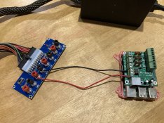
Made my first mistake today (at the same time reinforcing why the RPi cheap route was a good way to go!)...My ATX power breakout board finally arrived from Wish. Fantastic I thought, now to hook my PSU up to it and wire it into my RPI-28D+ to get this thing cranking. I hooked everything up, turned it on and nothing. This specific ATX breakout had fuses on all the output lines, and my mind went straight to that. Checked fuses and saw 5A, my stomach sank recalling something about a 1A fuse. Read the manual and sure enough it's 1A and not 5.

On the positive side, it didn't fry the Raspberry Pi.

🤷🏼‍♂️
 

LeighH

New elf
Joined
Apr 22, 2018
Messages
29
Amps won't be your issue, 1 amp for RPi is minimum required 2.5 is better, less than 1 & it will have problems, 5 amps just gives you head room.
Voltage is the big one, They need 5volts not 12, which is what I would expect the ATX out is,

**Edit I thought it was straight into the pie I see now the rPi-28D+ is a cape which is fine with 12v
 
Last edited:

Skymaster

Crazy elf
Global moderator
Generous elf
Joined
Dec 19, 2021
Messages
1,066
Location
Western Sydney
If you're coming from an ATX power supply, any of the RED wires will be +5V. Yellows are 12V.
So you can always tap into that to get 5V direct from the PSU.

The purple wire is 5V Standby (Purple wire), which is always active when the PSU has AC power (and not fully switched on), you could use that signal to power the pi, if you want the Pi to be able to turn the PSU on and off as Pixel power.
 

Freman

Uh Oh Elf
Generous elf
Joined
Aug 9, 2021
Messages
118
Sorry if I've misread but it sounds like you're measuring the current from + to -, please don't make the mistake of measuring that, measure the current through the load or you risk blowing the fuses in your meter.

Just make sure your 5v for the pi (usually the red wire on an atx supply) is fused at 1 (or 2.5 amps, if you find the 1 blows then get a 2.5)
 
Last edited:

Croydon Lights

Full time elf
Generous elf
Joined
Jan 6, 2018
Messages
101
No separate 5v supply is required for the Pi as it receives its supply from the rPi-28D+ and will take 12v just make sure its connected to the correct terminals Connecting 12V to the 5V power input will damage components on the pcb and may damage the Raspberry Pi. Connecting 5V to the 12V input will cause the board to not work due to insufficient voltage. Connecting the power in reverse can also damage the board and Pi
 

DaveRNZ

New elf
Joined
Nov 30, 2020
Messages
19
Thanks all. The RPI-28D+ manual says you can power the pi and the hat from the input block on the hat. It takes 12v or 5v with 1a fuse for 12 and 2a for 5 (unless I’m reading things wrong. I had 12v hooked to the 12v connector and ground to the ground after triple checking.
 

DaveRNZ

New elf
Joined
Nov 30, 2020
Messages
19
PSU turned on, no lights etc from Pi but noticed the fuse on the ATX breakout pop.
 

AAH

I love blinky lights :)
Community project designer
Joined
Dec 27, 2010
Messages
4,193
Location
Eaglehawk
Can you post a pic of everything wired up or email me a pic if you can't.
 

TerryK

Retired Elf
Joined
Feb 9, 2020
Messages
655
Location
West Central Ohio
As @AAH mentioned, I too am curious about how the devices are/were wired. Presuming the hardware is not or was not defective; and you've already indicated that 12V and Ground were properly connected; something else would seem to be the cause of the fuse opening. Have a PC connected to the RPi by chance?

@Freman "measure the current across the load" Uhmmm; voltage across, current/amperage through a or inline with.
 

DaveRNZ

New elf
Joined
Nov 30, 2020
Messages
19
Here’s a pic of it wired up. I don’t think it’s a faulty board, it worked fine when I did the initial setup with the Pi and hat powered via the Pi USB.

It’s likely just a dodgy power board. Next time I will run straight off the PSU.
 

Attachments

  • A8CF364C-8046-44B0-BE39-E883794E9E7E.jpeg
    A8CF364C-8046-44B0-BE39-E883794E9E7E.jpeg
    1.1 MB · Views: 29

Skymaster

Crazy elf
Global moderator
Generous elf
Joined
Dec 19, 2021
Messages
1,066
Location
Western Sydney
Here’s a pic of it wired up. I don’t think it’s a faulty board, it worked fine when I did the initial setup with the Pi and hat powered via the Pi USB.

It’s likely just a dodgy power board. Next time I will run straight off the PSU.
Try connecting to the 5V output on the breakout, as well as the 5V input on the board, rather than 12V. Understanding of course that this wont drive 12V pixels, but it's a test...... See if that works. If so, it's the voltage regulator on the PiHat that's crapped out.
 

AAH

I love blinky lights :)
Community project designer
Joined
Dec 27, 2010
Messages
4,193
Location
Eaglehawk
I hate being called a newbie :( It is my mistake though. The diode D1 is inserted back to front.
This diode is to protect the board and Pi if the 12V is put around the wrong way.
The good news is that the board will work fine on 5V if you have it on that power board or if the diode is bridged out with a wire link or swapped around.
You can still run 12V pixels when running the board off 5V. There's 4 separate power inputs for the 3 pixel outputs and the board+pi.rpi-28d diode.jpg
 
Top