Problem speed effects

Aurelien26

New elf
Joined
Oct 11, 2024
Messages
5
Hello !
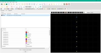
I'm actually working on 8x relays with D1 mini to do an show for begin. I've installed xLights and Vixen for compare. In first view i prefer Vixen for his simple interface and effects, xLight looks most complete but more difficult for a beginner (like me).
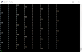
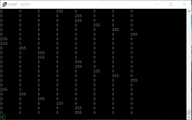
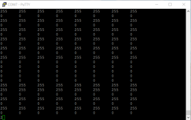
I've seen a trouble when i select an speed effect like "strobe" or "chase" with small time play. The light relays have some freeze due to lost packets in streaming or lags in software.
In xLight with same configurations for the DIY controller (D1 mini) i haven't this problem..
Does anyone know why it does that?
Thanks for help 😄
 
Post your code and I (and probably some others) will take a look. Also some screenshots of the config/patching in Vixen.
 
Ok, this is the code what i've modified (i'm not the author) :
C++:
/**
  Source of original code (Author) : https://lunardenlights.com/2020/08/d1-mini-e1-31-dmx-relay-controller/
  Modified by me (Aurelien26)
  Date : 07/10/2024

  This code is set for using 8x relays by sACN E1.31 (DMX control) using PWM outputs (analogWrite)
  For Softwares be like Vixen lights / Xlights or other using sACN E1.31
  Hardware(controller) : D1 mini (ESP8266)
**/

#include <ESP8266WiFi.h> // a library to include
#include <E131.h> // a library to include https://github.com/forkineye/E131

//Set your WiFi network information below...
const char* ssid = "xxxxx"; // your network AP SSID
const char* password = "xxxxx"; // your network AP password

//Set the universe and channel you want to use. Universe is E1.31 (DMX) universe.
//Channel will generally be 0, which is actually 1 (Red) in DMX. Use 1 for Green, and 2 for Blue.
const int universe = 1; // universe to listen to

const int channel_1 = 0; // channel to use - these are 1 lower than normal (0 = 1)
const int channel_2 = 1;
const int channel_3 = 2;
const int channel_4 = 3;
const int channel_5 = 4;
const int channel_6 = 5;
const int channel_7 = 6;
const int channel_8 = 7;

// Un-comment the following if not using DHCP, and edit accordingly.
// Important: Those are commas, not periods!!! This is just the way the IPAddress datatype works.
const IPAddress ip(192,168,x,10);
const IPAddress netmask(255,255,255,0);
const IPAddress gateway(192,168,x,1);
const IPAddress dns(192,168,x,1);

int channel_val; // the current value of the channel we are using, don't change this.
long int num_ch_in_pkt; // number of channels in the recieved packet, don't change this.

// names the ESP8266 GPIO output pin we are using (5 is D1 !!!)
int output_1 = 5; //D1
int output_2 = 4; //D2
int output_3 = 0; //D3
int output_4 = 2; //D4
int output_5 = 16; //D0
int output_6 = 14; //D5
int output_7 = 12; //D6
int output_8 = 13; //D7

E131 e131;

void setup() {

  Serial.begin(115200);
  Serial.print("Connecting to ");
  Serial.println(ssid);

//If you want to use a fixed IP address instead of DHCP, un-comment the following...
  WiFi.config(ip, gateway, netmask, dns);

  WiFi.begin(ssid, password);
  while (WiFi.status() != WL_CONNECTED) {
    //Loop (forever) until WiFi is connected.
    delay(500);
    Serial.print(".");
  }
  //* added showing ip for testing static ip
      Serial.println("");
      Serial.println("WiFi connected");
      Serial.println("IP address: ");
      Serial.println(WiFi.localIP());
  //*

  //Set output pin and set it high (it's off for active low).
  pinMode(output_1, OUTPUT); // set pin as an output
  pinMode(output_2, OUTPUT);
  pinMode(output_3, OUTPUT);
  pinMode(output_4, OUTPUT);
  pinMode(output_5, OUTPUT);
  pinMode(output_6, OUTPUT);
  pinMode(output_7, OUTPUT);
  pinMode(output_8, OUTPUT);

  digitalWrite(output_1, HIGH); // set pin to high (it's off for active low)
  digitalWrite(output_2, HIGH);
  digitalWrite(output_3, HIGH);
  digitalWrite(output_4, HIGH);
  digitalWrite(output_5, HIGH);
  digitalWrite(output_6, HIGH);
  digitalWrite(output_7, HIGH);
  digitalWrite(output_8, HIGH);
 
  // See below to set Multicast or Unicast. Default is multicast.
  // **** Pick one. You can either use Unicast or Multicast. If you don't know which- pick Multicast. ****
  e131.begin(E131_UNICAST, universe);   //Unicast (UDP)
//  e131.begin(E131_MULTICAST, universe); //Multicast (TCP)
}

void loop() {

// Bits stream going 0 at 255 for sACN E1.31 in DMX.
  num_ch_in_pkt = e131.parsePacket(); // parse packet
  if (num_ch_in_pkt) {

    // relay 1:
      channel_val = (e131.data[channel_1]);
      Serial.println(channel_val);                     
      analogWrite(output_1, channel_val);   // PWM

    // relay 2:
      channel_val = (e131.data[channel_2]);
      Serial.println(channel_val);                   
      analogWrite(output_2, channel_val);   // PWM

    // relay 3:
      channel_val = (e131.data[channel_3]);
      Serial.println(channel_val);                     
      analogWrite(output_3, channel_val);   // PWM

    // relay 4:
      channel_val = (e131.data[channel_4]);
      Serial.println(channel_val);                   
      analogWrite(output_4, channel_val);   // PWM

    // relay 5:
      channel_val = (e131.data[channel_5]);
      Serial.println(channel_val);                   
      analogWrite(output_5, channel_val);   // PWM

    // relay 6:
      channel_val = (e131.data[channel_6]);
      Serial.println(channel_val);                     
      analogWrite(output_6, channel_val);   // PWM

    // relay 7:
      channel_val = (e131.data[channel_7]);
      Serial.println(channel_val);                   
      analogWrite(output_7, channel_val);   // PWM

    // relay 8:
      channel_val = (e131.data[channel_8]);
      Serial.println(channel_val);                     
      analogWrite(output_8, channel_val);   // PWM
  }
}
And pics of controller configuration in Vixen and xLights softwares :
 

Attachments

  • Vixen controller config 1.PNG
    Vixen controller config 1.PNG
    121.7 KB · Views: 1
  • Vixen controller config 2.PNG
    Vixen controller config 2.PNG
    22.2 KB · Views: 1
  • Vixen controller config 3.PNG
    Vixen controller config 3.PNG
    120.3 KB · Views: 1
  • xLights controller config 1.PNG
    xLights controller config 1.PNG
    119.7 KB · Views: 1
  • xLights controller config 2.PNG
    xLights controller config 2.PNG
    133.5 KB · Views: 1
Looks like a reasonable sketch for either Vixen or xLights.

What type of relay are you using and what are you controlling? Likely not a PWM capable relay and AC lights? If so, your Write statements in the loop should be digital and have code similar to this.

if (channel_val <= 127) {
digitalWrite(channels, LOW);
}
else {
digitalWrite(channels, HIGH);
}

The LOW and HIGH might be reversed depending on your relay. Depending on what you are sending, trying to PWM AC relays would likely lead to unexpected results. So, unless xLights and Vixen are being sequenced to send the exact same data, I would say that maybe the difference is what data is being sent.
 
Yes is for AC 220V lights.
In first use i've used SRD05 relays (Low level) and changed it for SSR High level relays (omron g3mb-202p).
I've modified with "analogWrite" for use dimming light effects but, you're right, i think it's bad idea for AC relays use..
I will try these two codes (anagodWrite and digitalWrite) when the electrical box will be finished.
And for data sending between vixen and xlights, in my opinion it's not same method of transmission.
 
g3mb-202p relays are zero cross relays so smooth and predictable dimming will not work with them. It might be possible to turn them on or off per half cycle but that would require a very different control mechanism probably with a zero cross detect circuit. And it might end up with strobing. Depending on the lights attached, you may or may not see the strobing.

What does the serial monitor show for the two methods of transmission for the same effects? Are you seeing identical values?
 
Back
Top