P5 panel setup

joeyschinella

New elf
Joined
Dec 5, 2018
Messages
29
looking to get some p5 panels
seeing what i need to get up and running .
controllers/ boards etc

my current setup up is mainly hanson boards

thanks
 
I’m a bit confused. Can the panels be connected to a Colourlight card and then straight into a switch connected to the PC? Or does it need the panels to go through a Colourlight card, connected to a raspberry pi and then into a switch connected to the PC?
 
Generally it would go Show Master - Network - PI - Panel. In the most basic of setups you would go from an FPP PI to the Colorlight card. The PI can be you Show master or another PI, I have multiple PIs driving different panels. There can be more advanced situations also.
 
You wouldnt want a switch / home network between the colorlight card and whatever is driving it - this should be a dedicated link.
The reason is the underlying communications method is crazy basic; it will flood the colorlight packets throughout your entire network and bring it to a halt.
 
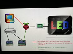
Sorry guys but I must be missing something. I have drawn up how my set up is with 2 options that I can see. The Red option where the FPP bypasses the switch has a problem in that the PC only has one network output which is currently used for my network switch and the Falcon controllers.

With the Green option I have the FPP connected to one of the network ports on the Falcon. Is it the green option or some other configuration?IMG_1133.jpeg
 
You need two network connections on the Pi.
One goes to your switch. This is the same as plugging it into a Falcon (which has inbuilt switch)
Second goes to the colorlight.

This will necessitate a USB network interface to be used for one of the two connections.

With the Pi connected to the switch, it will be visibile from the PCs and also be able to communicate the falcons
The second NIC to the colorlight will be dedicated for that purpose.
 
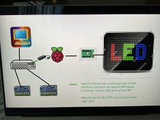
Thanks Skymaster, I think I understand. I have updated the diagram with the setup. If correct, then it might also help someone in the future
 

Attachments

  • IMG_1134.jpeg
    IMG_1134.jpeg
    658.8 KB · Views: 21
Bingo

On the topic of which NIC goes where - if the Pi is a 3b or less the onboard NIC is only 100Mbps and won't work with colorlight. The USB NIC will need to be gigabit and be used for the colorlight.
The Pi 3b+ and 4 onwards all have gigabit NICs onboard, so they can be connected to the colorlight
 
Now another question please. I have 20 panels in total (5 high x 4wide) and plan to run them at 30% power. I think I will need 2 350W power supplies.

OPTION A - 1 will power the first 2 rows (8 panels) and the other will power the other 3 rows.
OPTION B - have each PS a power 10 panels each which sounds like a better option, but will the negatives on the PS need to be joined as panels 11 and 12 will be getting power from PS 1 and 2? Or do the panels just pass through the data through the ribbon cables onto the next panel?
 
Normally you would think of powering them in columns. Column 1 and 2 on power supply 1, column 3 and 4 on power supply 2. Data will just pass through the data channel, and you just need to pick which one of the power supplies will power the colorlight card. The power cables for panels are designed to power 2 panels at a time with a short pigtail. Not a lot of extra length to work with unless you do something special. The color light card can be powered by the terminal lugs or a pin connector that uses the same one that are on the panels. I personally just made power leads with terminal connectors and used the lugs.
 
Power and data can be considered separately. Data would flow in rows, with 5 outputs from your Beagle or Colorlight. Power can be organised whichever way you like.
but will the negatives on the PS need to be joined as panels 11 and 12 will be getting power from PS 1 and 2?
This is done via the HUB75 cables. You dont need to worry about doing it at a PSU level.
 
Back
Top