Last pixel "slow" (WS2818)

macmanluke

New elf
Joined
Oct 31, 2024
Messages
8
New to RGB pixel christmas lights this year but fairly competent with electronics / rgb pixels in other use cases

Just finished building 2x Spiral Trees with starts on top
70 pixel tree - Raywu seed pixels 4 wire 50mm spacing 12v WS2818
joined to (soldered + heatshrink)
50 pixel star - Raywu seed pixels 4 wire100mm spacing 12v WS2818
controlled with a baldrick board
xconnect connectors

All finished tonight and testing it (had tested the components as i built it and didnt notice the issue then)
Have an issue where the last pixel in the star is "slow" changing colour a fraction of a second after the rest
Happens with 1 tree or 2
had 11v at the end of the string with no power injection with both trees
Tried power injection both ends of the strings - both 1 or 2 trees.
Same from xlights, test mode on baldrick, test mode in FPP

Possibly started after i ran the output wire from the top of the tree to the bottom (about 1.2m of 4 core alarm cable)
Didnt notice it before but i also didnt look at it that hard, maybe interferance?
Is there anything like a end of line resistor or something needed?

Dont think its a wiring issue or bad pixel as both behave exaclty the same

Any suggestions welcome

another thing i noticed is the 100mm spaced pixels seem to go full white if they lose data (but not super easy to replicate) - didnt think that was a WS2818 thing?
 
There's no resistors that go at the end of the line.
If you leave most things off is the behaviour replicated if you turn on about the last 10 pixels?
What version firmware is on your Baldrick?
 
There's no resistors that go at the end of the line.
If you leave most things off is the behaviour replicated if you turn on about the last 10 pixels?
What version firmware is on your Baldrick?
Ill give that a go tonight and see what that does
Latest firmware update
Was also considering trying a test with an ESP32 running WLED as a test, doubt its the controller but easy test.
 
Had another thought - i connected the data and backup data together on output is that actually ok? or should they only be joined on input?
 
Not used the 4 wires yet but my guy feeling is they should be connect at the controller output. Should be easy to find a wring diagram??
 
yea they say to connect them together at the controller - so i assumed they could be linked further along the chain but maybe not - i have asked the question.
If the backup and data cant be joined i guess the backup just gets left open going into a 3 pin xconnect at the end of the string.

Did a bit more testing tonight
same behaviour with last 5 or 10 pixels only
added an extra pixel to the end of the string, last pixel in the star is still slow.
 
Had another thought - i connected the data and backup data together on output is that actually ok? or should they only be joined on input?
Neither.
At the start of the string, Backup data should be tied to ground.
At the end of the string, both data and backup data should be disconnected.

Backup data output is actually directly connected inside the pixel to Primary Data Input. So by tying Primary Out to Backup out, you're connecting Primary out to Primary in, causing a data loop

So:
When going from the end of a string to a 3 wire pigtail, connect Positive, Ground and Primary Data out into the pigtail. Do not connect Backup out at all.
When connecting a 3 wire pigtail to input, connect Backup Data In and Ground together.

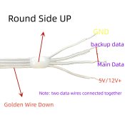
This is the diagram according to the supplier but do think i need to cut the backup wire at the end of the string.
S0c354f65a6054777b53ba4bc85f58552G.jpg

Did also just test on a esp32 with wled and it didnt seem to be as bad, not sure why.
 
There is certainly no harm to connect the two at the start of the string.The only issue you may see is that if there was a reason for it the first pixel to pick backup data over primary data, it'll shift all pixels to the left by one, (assuming 1 to n left to right), so Pixel 1 will show Pixel 2's data, 2 will show 3, 'n' will show 'n+1'......

I'd like to see the official data sheet though, vendors are sometimes wrong. What's the supposed chip used in them? WS2815? GS8208?

At the end of the string, you absolutely must NOT connect them together. As I mentioned before, you're causing a data loop and this would manifest itself exactly as what you're seeing.
 
1732793123888.png

This is the typical application circuit for GS8208. You can see here that from the controller, the signal goes into SDI of the first pixel, and SDI2 of the second. The output of the first goes into SDI of the Second, and SDI2 of the third.
Now if you were to look at the last pixel - connect the Blue backup and Green Data out - you'll be connecting SDO of the second AND third pixel to SDI of the third.

Also note SDI2 is grounded on the first pixel. That being said, there are one or two exceptions with it documented in the data sheet of a particular model where it shows both Primary & Backup tied together.
 
They are meant to be WS2818 but who knows if thats whats actually used.

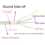
Just did a test and following diagram works (my addition in pink)
S0c354f65a6054777b53ba4bc85f58552G.jpg
Tried the opposite first but that was causing duplicate pixels (eg 2 pixels displaying same data)
Does that sound correct?

Be nice if they actually provided a complete wiring diagram,
surely im not the only one connecting 2 strings together (and making bad assumptions)
 
1732795072544.png

Dual data seeds run in pairs. You can see there's one here with a black arrow, and the other with a green diamond. Lets call these "A" type and "B" type.
When creating the pixel strips, the Chips are laid out on a continuous spook of wire. Then the wire between the "Backup In" and "Primary Out" on a pixel cut, as per the above.
By alternating the primary and backup data between the A and B types, it means they don't have to cut wires between every pixel, and they can have this notion that the Input to pixel one, also goes to the backup in of pixel 2.

So if you were to splice to the backup line, instead of the primary, you would be seeing the same data that the pixel before the splice saw. Which is why you get the duplication.
 
thanks that diagram is more clear and explains the issue im having tonight
Fixed one tree using the diagram i posted previously but then the second one behaved the opposite
Looking at that diagram - does that mean its possible every second pixel in a bulk spool flips backup / primary with no visual way of telling which is which once you start cutting it up?
Edit: Further testing seems both wires are inputs and outputs - both data wires will behave correctly if i connect them to the correct input (including simultaneously) but if they get flipped then you get the dup pixel issue. And must be A and B leds as its not consistent.
Seems like it would be smart to always work in even numbers of leds so your always working with an A + B pair

back up wire makes it a whole lot more confusing that regular 3 pin haha
 
Last edited:
Marked and cut up 4 pixels this morning and confirmed there is alternating pixels

Pixel 1:
G-----G
D2 D2
D1---D1
V-----V

Pixel 2:
G-----G
D2---D2
D1 D1
V-----V
 
Back
Top