Some 12V verse 5V musings... with some math...

nutz4lights

Full time elf
Joined
Dec 12, 2012
Messages
305
Location
Melbourne, Florida
I am pretty decent in regards to electrical stuff... so I am a bit stumped by where I sit tonight...

I posted in another thread about my first experience with 12V pixel strings, not strips. After finally getting them working with my P12R, I decided to measure the DC current running through the string with white illumination, which is the maximum current setting. I put my meter inline such as:

12V output from P12R --> meter red --> meter black out --> 12V input to string

I measured 3.80A for 93 lights which is 41mA (again, these are the 12V pixels, not strip). That is 14mA per color in R-G-B assuming that they all draw equally from the IC.

So I decided to try the same thing with a comparable square pixel 5V light string. I ran the same setup (although switching to my 5V power supply) for measuring as I did above. I measured 1.2A for a 50 count string using white illumination, which is 24mA and that is where I am lost.

Something must be wrong right? That is only 0.12W per bulb and these are supposed to be 0.3W aren't they?

This is all very important to me because I am finalizing designs for my display for the year and the power is obviously a huge part of deciding which way things will go... For instance: The P12R can handle up to 30A per bank of six outputs... that is up to 5A per bank. I was planning on running 100 pixels per output on all the outputs for a few different design elements (pixel megatree, pixel twig trees ,and pixel palm tree wrap) and with 0.3W x 100 x six = 36A at 5V and that means running power separate from the P12R... whereas... if the 100 pixel outputs really only draw 2.4A based on my measurements above... that is only 14.4A per bank on the P12R and I can run the power integrated with the P12R instead of using separate power supplies and cabling...

Thanks for reading... I look forward to the comments and discussion...
 
You will find measured currents are nearly always lower than rated currents, this is due to many reasons. Variation in resistor values, variation in LEDS, design specs being higher than real rated specs, construction differences and voltage drop along the string.
Try measuring the voltage at the end of the string when the string is white as well and see what the voltage is as you may be loosing some current there due to underdriving the LEDs due to voltage loss along the string.
 
ɟɐsʇǝppʎ said:
You will find measured currents are nearly always lower than rated currents, this is due to many reasons. Variation in resistor values, variation in LEDS, design specs being higher than real rated specs, construction differences and voltage drop along the string.
Try measuring the voltage at the end of the string when the string is white as well and see what the voltage is as you may be loosing some current there due to underdriving the LEDs due to voltage loss along the string.
I can do that (pertaining to the voltage measuring comment). I thought with only 50, I was safe in regards to voltage drop and underdriving the LEDs.

Btw, these are the 5V and 12V pixels that I posted measurements on...

http://www.aliexpress.com/store/product/WS2811-LED-pixel-node-DC5V-input-full-color-RGB-string-50pcs-a-string-IP68-rated-in/701799_677496152.html

http://www.aliexpress.com/store/product/DC12V-input-WS2811-pixel-node-100pcs-a-string-IP68-rated-with-all-black-wires/701799_762876648.html

Thanks.
 
Eddy... I don't know how I never noticed this sticky thread that you posted (I have seen the 12V versus 5V thread):

http://auschristmaslighting.com/forums/index.php/topic,3812.0.html

So those are all theoretical values... I think it would be interesting to have people post ACTUAL values for these strings. I have three different kind of pixel strings here (one "bullet" type and 5V, two "square" types in 5V and 12V) and can measure those... but I'd like to see what some others have measured.
 
Depending on the guage and length of the cable between the strip/string and power supply will determine the voltage that the string/strip starts with. So also test at the strip/string when its white, this will give you a good measurement to how much volts are being lost even before it gets to the string.

The issue with 5vdc is that the % of voltage drop over a distance is much higher than if it was using 12vdc in the same situation.
 
ɟɐsʇǝppʎ said:
Depending on the guage and length of the cable between the strip/string and power supply will determine the voltage that the string/strip starts with. So also test at the strip/string when its white, this will give you a good measurement to how much volts are being lost even before it gets to the string.

The issue with 5vdc is that the % of voltage drop over a distance is much higher than if it was using 12vdc in the same situation.
Ok. These were being measured with the pixels basically shooting right out of the P12R, so not much cabling present. I will keep the cabling in mind when doing the measurement. Actually, that RGB twig tree I posted about last week has cabling present (probably 2-3m) between the P12R and the tree... so I can use that for comparison... it will probably have higher voltage drop, which means lower voltage at Pixel 1, which most likely mean lower current draw due to further under-driving the LEDs... right?
 
nutz4lights said:
Eddy... I don't know how I never noticed this sticky thread that you posted (I have seen the 12V versus 5V thread):

http://auschristmaslighting.com/forums/index.php/topic,3812.0.html

So those are all theoretical values... I think it would be interesting to have people post ACTUAL values for these strings. I have three different kind of pixel strings here (one "bullet" type and 5V, two "square" types in 5V and 12V) and can measure those... but I'd like to see what some others have measured.

Actual values will vary from install to install and from batch to batch. I prefer to work from the specs as this will guarentee a system that is designed well within the limits of the system and be able to handle the majority of spikes and variations that a system may typically see.
 
nutz4lights said:
ɟɐsʇǝppʎ said:
Depending on the guage and length of the cable between the strip/string and power supply will determine the voltage that the string/strip starts with. So also test at the strip/string when its white, this will give you a good measurement to how much volts are being lost even before it gets to the string.

The issue with 5vdc is that the % of voltage drop over a distance is much higher than if it was using 12vdc in the same situation.
Ok. These were being measured with the pixels basically shooting right out of the P12R, so not much cabling present. I will keep the cabling in mind when doing the measurement. Actually, that RGB twig tree I posted about last week has cabling present (probably 2-3m) between the P12R and the tree... so I can use that for comparison... it will probably have higher voltage drop, which means lower voltage at Pixel 1, which most likely mean lower current draw due to further under-driving the LEDs... right?

Yes if all things are equal besides the distance

This thread will explain the results of voltage drop http://auschristmaslighting.com/forums/index.php/topic,3668.0.html
 
Just to add some more information here... Tonight I went and soldered pigtail connectors on two more strings. These are 5V WS2811 bullet-type 50 pixel strings and the spacing is higher between pixels (20cm instead of 10cm). These are the same as I have on the RGB twig tree I posted about in a separate thread. I connected the two strings together to make a 100 count string. Pixel 1 is connected right out of my P12R and Pixel 100 is connected to a separate 5V power supply.

I measured DC current flowing with white on the light and saw 0.85A in the one string and 0.95A in the second string. I also measured the current draw in a comparable string mounted on my RGB twig tree which had a 2-3m cable between the P12R and the tree and saw 0.80A for white.

I still can't help but think that this is low so I decided to measure the DC current draw with red, green, and blue on. I only did this for the string that measured 0.95A for white above. I saw the following DC current draw values:

red: 0.6A
green: 0.5A
blue: 0.5A

Considering red has a lower voltage (2.2V) compared to green and blue (3.2V), I guess it makes sense that the red draws higher current to get the same power output...

So theoretically, to get white.... red, green, and blue all have to be on, which should draw 1.6A and I am only drawing 1/2 of that... so the mystery continues...

For comparison, the 5V WS2811 string I mentioned in the first post of this thread was a 50 pixel string of the square-type pixels and it had the more conventional 10cm spacing as opposed to 20cm spacing for the strings mentioned in this post... and the DC power draw for that square-pixel string was 1.2A directly out of my P12R... so the smaller pixel spacing, which means shorter total string length and lower cable resistance, had higher current draw inevitably due to less under-driving going on...

And the 12V string mentioned in the first post was drawing roughly 2.0A per 50 count string... so there is obviously a heck of a lot less under-driving going on there as well... the next test I want to do is to compare a 50 count of 12V pixels to a 50 count of 5V pixels of the type I have received from Ray... technically if the current draw is lower on the 5V pixels, there is some chance that they are not as bright...

Hope someone get's some useful information out of all of this... I'd be curious to see others measuring the current draw of their pixels and comparing it to what I've measured above...
 
You need to measure the voltage at the end of the string to see if voltage drop is effecting your results, but as mentioned before, specs are just about always higher than measured. All total current draw tests should be done when the LED is white as this is the full load and will show if there is any voltage drop that could be effecting your result
 
nutz4lights said:
I still can't help but think that this is low so I decided to measure the DC current draw with red, green, and blue on. I only did this for the string that measured 0.95A for white above. I saw the following DC current draw values:

red: 0.6A
green: 0.5A
blue: 0.5A

Considering red has a lower voltage (2.2V) compared to green and blue (3.2V), I guess it makes sense that the red draws higher current to get the same power output...

So theoretically, to get white.... red, green, and blue all have to be on, which should draw 1.6A and I am only drawing 1/2 of that... so the mystery continues...

When the total current draw (all white) is substantially less than the sum of the R, G & B colours, that's an indication that there is excessive voltage drop in pixel power wiring.

The Vf (forward voltage) difference in the LED colours is not a reliable indication of any current drive requirements to achieve the same light levels. The light output is determined by the manufacturing process and chemistry.
 
OK, I had some time to do some major work on this tonight and really put my head into the math behind what I'm seeing and I think this will be useful for others. Please see above for more about what I'm doing, but basically, I am trying to understand REAL current draw through two types of 5V WS2811 50 count pixel strings from Ray Wu (4" spaced square-type and 8" spaced bullet-type) connected DIRECTLY do an ECG-P12R. My reasoning behind attaching directly to the ECG-P12R is trying to understand the performance of JUST the pixel string.

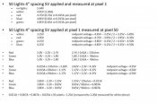
So, the first set of measurements is all shown in the picture below. These measurements are for the 4" spaced square-type pixels. The top set of measurements is the voltage present at Pixel 1 (measured at the power supply) with a particular color on the string. I also show the steady state DC current that is flowing through the string with each of those colors, both for the entire string and per pixel obtained by dividing by 50. The second set of numbers shows the voltage measured at the end of the 50 count pixel string which shows how much the voltage has dropped by the end of the string for each color. I then go on to perform some calculations that Eddy has in one of the main stickies that is of critical importance to having a clue on how to do all of this. First calculating the presumed resistor value for each of the three legs, then back-calculating actual dropping voltage based on the measured current, followed by the presumed midpoint voltage of the string based on that dropping voltage and the theoretical forward voltage of the individual LEDs. The last set of numbers takes the midpoint voltage of the string with white illumination and calculates the theoretical current that one would expect to see using the resistors calculated earlier... and comparing this to the actual current that is measured with white illumination. As you can see, there is pretty good agreement between the calculated current draw and what was measured.
[attachimg=1]

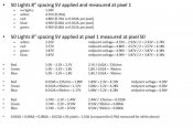
This next picture shows the same thing as above, but for the higher spaced bullet-type pixel strings. My methodology was the same as above. The current draw result was not quite as close as the square pixel example above and I am going to assume that it is due to the higher spacing between pixels causing some non-linearity, which would basically skew my use of the "assumed midpoint voltage" portion of my calculation.
[attachimg=2]

As always, I am curious for input and suggestions based on going through the calculations. I realize that adding extension cords between the P12R can contribute additional skewing of the results, but my understanding is that if you keep the gauge of the extension cord thicker and the distance down, the string should drive most of the voltage drop.

I am at the point where I'm getting ready to place a large order with Ray Wu and I am doing this because I want to have a good understanding of logistically how I'm going to connect 100's of these strings strings... what type of connectors, how many power supplies, interface design to the P12R and/or auxiliary power supplies... etc.
 

Attachments

  • 5V 50 square pixel.jpg
    5V 50 square pixel.jpg
    56.3 KB · Views: 142
  • 5V 50 bullet pixel.jpg
    5V 50 bullet pixel.jpg
    56.5 KB · Views: 145
The 8 inch results show why your current is lower on this string. The forward voltage on the LEDs are approx 3.1v for green and blue and around 2.1 v for Red. The volatge at the end of the string is too low to be able to maintain the correct current for the LED when white and i would expect that you may see some pinking of the last few pixels in this string

The constant current driver will maintain the correct current as long as the voltage is not high enough for it to be able to produce that current and with the 8 inch example then at the end of the string you will find that the CC driver cannot maintain the correct current due to the volatge drop that you have measured and this will affect your results.
 
<I just realized that I forgot to perform the customary "stupid U.S. units to the units the rest of the world uses" calculation... in the charts above, obviously the 4" are the 10cm spacing and 8" are 20cm spacing>

Eddy,

So its safe to say at this point that the only difference between the two strings is the length of wire between pixels and the resultant total length of the string. They both use 20AWG wire between pixels and I assume they are using the same RGB element and WS2811 IC.

I'm sure you remember this Eddy but the 20cm spaced strings were used on that RGB twig tree I had created a post for a few weeks back. The reason for the 20cm between pixels was because of my estimate for the amount of wire I would need to successfully make it out to the tip of the branch and back into the center of the tree to move on to the next branch. I am thinking at this point that I may want to shorten that 20cm distance, but I'm not sure I can shorten it all the way to 10cm... I don't think it will work on the tree... should I try to request 18AWG cable from Ray? Just leave things alone and deal with the color? Inject power every 40 pixels instead of 50? I guess the other option would be to switch to 12V.
 
The options are

1: Shorter space between pixels. This will still not really help because the distance you require will still be the same but instead you will have more lights and thus more load to consider which means more voltage drop

2: Larger diameter to 18 guage. This is another alternative but the fact that you will still need injection regardless when hooking in additional strings makes this option somewhat a waste of money

3: Inject in between each string, no need to inject back at 40 as you will also be back feeding the 1st string if multiple strings connected. This is the best option for you. You will need to add injection at the end of the 3 strings as well.
 
Back
Top