5v 2811 pixels not testing correctly on P12R

Ktag

Apprentice elf
Joined
Dec 25, 2012
Messages
51
Location
North Brisbane
Hi all, I am just starting out (again), and trying to get some understanding. I am testing the strip lights I have purchased via the standard test pattern within the ECG-P12R controller.
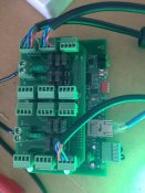

ECG-P12R
Setup for 12v one side and 5v the other.
12v power supply tested OK at 12v
5v power supply tested OK at 5v
Output to lights also checked OK 4.95v & 11.89v as appropriate


WS 2811 12v pixel strip testing OK.


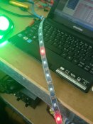
WS 2811 5v pixel strip not testing well.
16 pixel length = the 5th & 9th pixel only light up and are Red.
Rest of 5m length = 6th pixel only lights up in red
These have been split to see if it made a differencee - obviously not.


Could someone point me in the right direction to correct or source the problem. Could it be that the 5v light strip is bad?


Thanks
Glenn
 

Gilrock

Full time elf
Joined
Jan 4, 2013
Messages
439
Location
Tucson, AZ
Maybe post a screenshot of the String Config page for the P12R. Did you enable all the outputs and define the chip type and speed?
 

dale82

Senior elf
Joined
Nov 19, 2010
Messages
581
Location
Kingaroy
Are you able to post your string config etc. also where abouts in qld are you as someone nearby might be able to help
 

fasteddy

I have C.L.A.P
Global moderator
Joined
Apr 26, 2010
Messages
6,648
Location
Albion Park NSW
So as I understand it that the strip goes through the pattern but you have a couple of lights within the string that are stuck on Red. if thats the case and the other lights are working or working upto the faulty light then this could point to a hardware issue
BUT
Are you sure you are connecting to the input and not the output of the string
 

Ktag

Apprentice elf
Joined
Dec 25, 2012
Messages
51
Location
North Brisbane
Thanks


I have attached screenshot of config as well as photo of controller & offending lights. The lights do not run any pattern they simply only light up red the 6th & 11th pixel (staying lit), all others never come on. (I said in my original post it was the 5th & 9th, so either I generalised or they changed... not sure which!)


All wires double checked and are attached as per board or strip labelling.

[attachimg=3]
 

Attachments

  • IMG_1469.JPG
    IMG_1469.JPG
    122.1 KB · Views: 20
  • IMG_1468.JPG
    IMG_1468.JPG
    127.7 KB · Views: 23
  • Untitled.jpg
    Untitled.jpg
    146.2 KB · Views: 56

Gilrock

Full time elf
Joined
Jan 4, 2013
Messages
439
Location
Tucson, AZ
I use a speed of 3000 for the WS2811's but I'm not sure if that would make a difference. It would be nice to see a close-up photo of the cable where it attaches to the end of the ribbon. You are showing 4 wires on the P12R connectors and the WS2811 doesn't use a clock line so is the green wire not connected on the other end? Looks like you need to blue wire going to your data in.
 

Ktag

Apprentice elf
Joined
Dec 25, 2012
Messages
51
Location
North Brisbane
Thanks Gilrock, I have tried a few other speeds, 3000 being one of them, but no change. The 'green" clock is wired to controller only for neatness as I have 4 wire connectors but is not used at the other end. I have swapped each of the 2 5v lengths I have to each controller point but no change.


The 12v set I have on he other half of the controller is running just as expected, travelling through its test pattern correctly.


I am at Warner - North side of Brisbane.
 

Gilrock

Full time elf
Joined
Jan 4, 2013
Messages
439
Location
Tucson, AZ
I swear the pattern you are seeing looks similar to when I've hooked up 5V to a 12V string. Are you sure that string is 5V? I know you said you measured the power but maybe they gave you the wrong string or labelled it wrong. I once ordered a 12V power supply from Ray Wu and it had a 12V label but it was only a 5V supply.
 

logandc99

Dedicated elf
Joined
Jul 13, 2012
Messages
1,153
Sounds like your power supplies are correct if you are getting correct output voltage measurements (i.e 5v from the 5v side and 12v from the 12 volt side).
You seem to be getting some power out to the strips as you are seeing lights on but the data telling the lights to cycle through the sequence isn't getting through.

Are both lengths of 5v strip you are testing the same strip cut into two sep lengths or are that two completely different strips?

And when you said you swapped the two 5v lengths, did you mean you swapped them with eachother or swapped them with two other completely different 5v strips? If the former, would be worth checking with two completely different strips just to try and eliminate the problem being related to a fault in the original strip.


The only other things I can suggest is to try a few things to try to eliminate possible causes.
Maybe try different outputs on the 5v side to make sure it's not a fault with just those two outputs.
Also, to eliminate a problem in the pigtails, try using the pigtail that works on the 12v side over on the 5v side and if the problem remains, then you have eliminated faulty pigtails as a cause.
By the way, I noticed one fuse is missing from the 5v side, (output six I think). Was there are reason for that?


Just a couple of suggestions from my very limited electronics/ P12s experience. :)
 

fasteddy

I have C.L.A.P
Global moderator
Joined
Apr 26, 2010
Messages
6,648
Location
Albion Park NSW
A little word of caution is ensure you power down the controller before connecting and disconnecting lights as the 2811 and 2812 have a known issue where if they are plugged in when the controller is running then you run the risk of damaging the first pixel chip. Have you been doing this? because if you have you may have damaged the first pixel

So looking at your strip it appears to be a 5v 2812b strip, so the voltage should be correct if you are putting 5vdc through.
 
Top