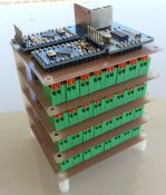
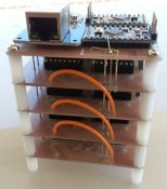
Following on from the Arduino based Pixel controller I posted yesterday, I would like to share my work on a dumb pixel controller i completed some time ago.
The breakdown cost per module is something around the $30-$40 mark depending on your skills and resourcefulness.
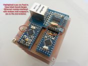
This one is based on 2 arduinos - One handles all of the E1.31 stuff and the other controls an array of shift registers. They speak to each other via i2c.
Why 2 arduinos? The main reason is that the shift registers need to use the SPI port and so does the ethernet module - The arduino only has one SPI port. It also allows the PWM stuff to be offloaded for faster operation.
Is this the best way to do it? Probably not but it works and is cheap. I have built 4 of these and they work well. See the end of this post for possible improvements/warnings etc. Also note that the ones I built were the first prototypes and are not the exact designs posted here. The pictures represent the initial design.
So, on to the show...


The boards were designed in sprint layout, there is a free viewer available from Abacom which enables you to print them out for etching your own PCBs but these particular ones were isolation routed on a CNC machine.
Parts sourcing
Each 'cube' requires:
2 X Arduino Pro Mini http://www.aliexpress.com/item/Free...e-Media-ATMEGA328P-5V-16M-for/1832692835.html
1 X ENC28J60 Ethernet module http://www.aliexpress.com/item/ENC2...-LPC-STM32-3-3V-free-shipping/1334967553.html
8 X 74CH595 Shift Registers http://www.aliexpress.com/item/Free...C595N-74HC595N-74HC595-DIP-16/1570657157.html
16 X PMV16UN FETS http://au.element14.com/jsp/search/productdetail.jsp?SKU=1894627RL
32 X Right angle 2 way push connectors http://www.aliexpress.com/item/Free...onnector-Spring-termnal-block/1894179668.html
8 X 0.1uf Capacitors - Jaycar $0.4 each (or source some cheaper ones)
PCB - Jaycar sell a large sheet that is enough to build 4 of these for about $20
*** Note: The Arduino pro mini and ethernet modules are specific ones and not 'generic'. The ethernet module has an onboard 3.3v regulator so it will run from 5v and the arduino has a slightly different pinout from most pro minis. There's no reason this can not be changed but for 'plug-n-play' you will need these ones.
*** Note 2: These FETS are TINY. You will need a good soldering iron and a steady hand to be able to solder them. The technique I used was to tin the middle pad on the PCB and then use fine point tweezers to locate the FET in place and 'reflow' the solder to the middle pin. This is then enough to hold the chip in place to solder the remaining 2 pins, then come back to the middle pin to make sure it's properly soldered.
For final assembly I used some PCB risers from Jaycar but they are very expensive ~$10 for 25, I would suggest sourcing them from elsewhere.
I also used some 'pins' from an old multi-level PCB for the power, data and ground plane connections between the boards. Use what you want there. I have made the pads on the 5v and Gnd connections very large to allow for larger holes to be drilled for higher current capability.


PCB Files
http://woodcroftlights.info/files/Top Board.LAY
http://woodcroftlights.info/files/Sub Board.LAY
Arduino Sketches
http://woodcroftlights.info/files/ENC28J60_sACN_Rx.ino
http://woodcroftlights.info/files/slave_receiver.ino
Notes:
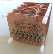
As you can see, in the picture from the bottom, I have added a fillet of solder to the ground plane to increase it's current handling ability. I have not tested these modules at full capacity but in theory, each channel is capable of switching about 5A at up to 20v. Do not go past these values or expect a slightly different type of light display.
If someone wanted to redesign the system, another way that could be more efficient would be to remove the 2nd arduino and replace the shift registers with WS2811 chips to drive the FETS instead. This might work better but would likely drive the price up.
I am not happy with the ground plane connections to the back set of FETs - Its a bit messy but it works. I used bent over PCB header pins to link them all. There is also a connection to the Capacitor in the middle of the board to connect with it too (red lines)
There is no protection from spikes, reverse polarity, interference etc. You may need to add capacitance on the main power feed to smooth power to the module and be extra cautious with power connections.
Ensure that if you are using multiple power supplies/voltages that all of the ground planes are tied together - For my setup I am using PC power supplies (or more specifically SERVER power supplies) capable of almost 100A on 12v rails and about 60A at 5v. These already have common ground between the output voltages.
Disclaimer: I am not an Electronic engineer, nor do I claim to be an expert of any sort in this subject. This information is provided as-is with no warranty of any kind, It's just something that works for me. You may not have the same results. I am not responsible for how you use this information in any way. (Reminds me of the Vixen license disclaimer)
The breakdown cost per module is something around the $30-$40 mark depending on your skills and resourcefulness.
This one is based on 2 arduinos - One handles all of the E1.31 stuff and the other controls an array of shift registers. They speak to each other via i2c.
Why 2 arduinos? The main reason is that the shift registers need to use the SPI port and so does the ethernet module - The arduino only has one SPI port. It also allows the PWM stuff to be offloaded for faster operation.
Is this the best way to do it? Probably not but it works and is cheap. I have built 4 of these and they work well. See the end of this post for possible improvements/warnings etc. Also note that the ones I built were the first prototypes and are not the exact designs posted here. The pictures represent the initial design.
So, on to the show...


The boards were designed in sprint layout, there is a free viewer available from Abacom which enables you to print them out for etching your own PCBs but these particular ones were isolation routed on a CNC machine.
Parts sourcing
Each 'cube' requires:
2 X Arduino Pro Mini http://www.aliexpress.com/item/Free...e-Media-ATMEGA328P-5V-16M-for/1832692835.html
1 X ENC28J60 Ethernet module http://www.aliexpress.com/item/ENC2...-LPC-STM32-3-3V-free-shipping/1334967553.html
8 X 74CH595 Shift Registers http://www.aliexpress.com/item/Free...C595N-74HC595N-74HC595-DIP-16/1570657157.html
16 X PMV16UN FETS http://au.element14.com/jsp/search/productdetail.jsp?SKU=1894627RL
32 X Right angle 2 way push connectors http://www.aliexpress.com/item/Free...onnector-Spring-termnal-block/1894179668.html
8 X 0.1uf Capacitors - Jaycar $0.4 each (or source some cheaper ones)
PCB - Jaycar sell a large sheet that is enough to build 4 of these for about $20
*** Note: The Arduino pro mini and ethernet modules are specific ones and not 'generic'. The ethernet module has an onboard 3.3v regulator so it will run from 5v and the arduino has a slightly different pinout from most pro minis. There's no reason this can not be changed but for 'plug-n-play' you will need these ones.
*** Note 2: These FETS are TINY. You will need a good soldering iron and a steady hand to be able to solder them. The technique I used was to tin the middle pad on the PCB and then use fine point tweezers to locate the FET in place and 'reflow' the solder to the middle pin. This is then enough to hold the chip in place to solder the remaining 2 pins, then come back to the middle pin to make sure it's properly soldered.
For final assembly I used some PCB risers from Jaycar but they are very expensive ~$10 for 25, I would suggest sourcing them from elsewhere.
I also used some 'pins' from an old multi-level PCB for the power, data and ground plane connections between the boards. Use what you want there. I have made the pads on the 5v and Gnd connections very large to allow for larger holes to be drilled for higher current capability.
PCB Files
http://woodcroftlights.info/files/Top Board.LAY
http://woodcroftlights.info/files/Sub Board.LAY
Arduino Sketches
http://woodcroftlights.info/files/ENC28J60_sACN_Rx.ino
http://woodcroftlights.info/files/slave_receiver.ino
Notes:
As you can see, in the picture from the bottom, I have added a fillet of solder to the ground plane to increase it's current handling ability. I have not tested these modules at full capacity but in theory, each channel is capable of switching about 5A at up to 20v. Do not go past these values or expect a slightly different type of light display.
If someone wanted to redesign the system, another way that could be more efficient would be to remove the 2nd arduino and replace the shift registers with WS2811 chips to drive the FETS instead. This might work better but would likely drive the price up.
I am not happy with the ground plane connections to the back set of FETs - Its a bit messy but it works. I used bent over PCB header pins to link them all. There is also a connection to the Capacitor in the middle of the board to connect with it too (red lines)
There is no protection from spikes, reverse polarity, interference etc. You may need to add capacitance on the main power feed to smooth power to the module and be extra cautious with power connections.
Ensure that if you are using multiple power supplies/voltages that all of the ground planes are tied together - For my setup I am using PC power supplies (or more specifically SERVER power supplies) capable of almost 100A on 12v rails and about 60A at 5v. These already have common ground between the output voltages.
Disclaimer: I am not an Electronic engineer, nor do I claim to be an expert of any sort in this subject. This information is provided as-is with no warranty of any kind, It's just something that works for me. You may not have the same results. I am not responsible for how you use this information in any way. (Reminds me of the Vixen license disclaimer)

