Every time I think I've got a decent understanding on handling power injection, I get some doubts, investigate that and return to square one and I'm confused once more.
Watching @lithgowlights present at the ACL mini in 2017 Here he suggests not to cut the +V as you will then have two pixels right next to each other potentially with different voltages and noticeable colour differences.
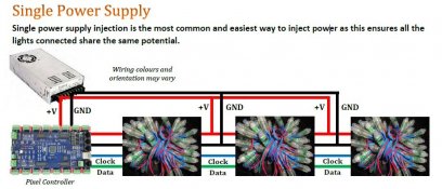
From the 101 there is this image:

Here there is no cutting of the wires and the only reason I can conclude is it's from one power supply and more importantly, no fuse between power supply and injection points.
Given the above, how should this be wired?

In the above, each injection cable comes from a distro board with fusing for each of the +V
This is something I am really not getting clearly and I want to move forward with wiring up my display, but this is critical that I clear this up before proceeding any further.
Watching @lithgowlights present at the ACL mini in 2017 Here he suggests not to cut the +V as you will then have two pixels right next to each other potentially with different voltages and noticeable colour differences.
From the 101 there is this image:

Here there is no cutting of the wires and the only reason I can conclude is it's from one power supply and more importantly, no fuse between power supply and injection points.
Given the above, how should this be wired?

In the above, each injection cable comes from a distro board with fusing for each of the +V
This is something I am really not getting clearly and I want to move forward with wiring up my display, but this is critical that I clear this up before proceeding any further.
Last edited:

