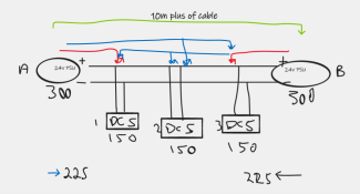
A question was raised in chat could the seemingly always on special, outdoor extension cords (AC) be used to run 24v around a display before dropping the voltage using DC-DC bricks at different props.
Questions raised:
Absolutely, Bunnings currently show these available in 25M lengths for $22. The have 3 x 1mm2 copper conductors. cut the molded plugs off, pair neutral/earth wires for ground and leave the brown active for positive.
using two wires for ground reduces the voltage drop (rise) on the ground wires which is better.
Compared to other options often available in AU this is reasonable cost effective.
4mm2 solar cable would be significantly better for this role though at a higher price.
How much Voltage drop?
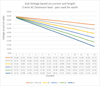
Here's the drop measurements using a electronic load at the end of a 10M run to get the baseline numbers all other numbers are calculated.

13A was the highest current measured as that was the limit of the 27v PSU I had on hand.
The common 12/24v DC-DC convertor handles 27v without issues under no load.
How many DC-DC bricks could be run?
This is a "depends answer" and for this we will largely use watts in the next lot of dot points.
Related then, how many pixels?
This is entirely based on the pixels power but at 100% white 5v pixels properly power injected will need around 4.4A/100 around 400 per 20A brick. so around 1200 per cable run.
runs then at lower brightness etc will increase this, often dramatically.
Want to do some further calculations based on the above cable then this is the magic constant as measured.
How does it work.
Scenario, 10m run with 10A
10m * 10a * 0.033071 = 3.3v drop
25m * 12a * 0.033071 = 9.9v drop
Cheers
Phil
Questions raised:
- Was it feasible?
- how much voltage drop was there?
- How many DC-DC bricks could be run?
- Related then, how many pixels?
- Pixels are constant current devices so power used is constant at 100% settings
- Current always leads to voltage drop.
- Using 24v and above for distribution is sensible but may not always be the best option.
- Voltage drop per metre per amp for cable is completely calculatable based on wire resistance.
- Voltage drop resulting from dc-dc bricks along a run results in non linear voltage drop, (just like pixel strings)
- Four convertors, one every 5M is completely different to 4 at the end of the run.
- It is essential you draw this up and even do some basic maths to see if it is suitable.
Absolutely, Bunnings currently show these available in 25M lengths for $22. The have 3 x 1mm2 copper conductors. cut the molded plugs off, pair neutral/earth wires for ground and leave the brown active for positive.
using two wires for ground reduces the voltage drop (rise) on the ground wires which is better.
Compared to other options often available in AU this is reasonable cost effective.
4mm2 solar cable would be significantly better for this role though at a higher price.
How much Voltage drop?
Here's the drop measurements using a electronic load at the end of a 10M run to get the baseline numbers all other numbers are calculated.

13A was the highest current measured as that was the limit of the 27v PSU I had on hand.
The common 12/24v DC-DC convertor handles 27v without issues under no load.
How many DC-DC bricks could be run?
This is a "depends answer" and for this we will largely use watts in the next lot of dot points.
- Every AC-DC or DC-DC convertor has an efficiency rating and this needs to be factored in.
- Modern DC-DC bricks can approach 97% but lets use 94% as a more likely average
- A common 350w PSU should deliver 320w all day everyday at 27v
- So a 100w (20A 5v) brick would need 106w input
- Three of these will be 318w required maxing out the PSU
- Place all of these at the end of the power run at 35M it will still work but is getting marginal.
- Place these at 10, 20 35 and the numbers get a lot better. subject of an update.
- Use a higher wattage PSU then voltage drop will become the prevalent issue and you will need to calculate it out.
Related then, how many pixels?
This is entirely based on the pixels power but at 100% white 5v pixels properly power injected will need around 4.4A/100 around 400 per 20A brick. so around 1200 per cable run.
runs then at lower brightness etc will increase this, often dramatically.
Want to do some further calculations based on the above cable then this is the magic constant as measured.
| V Drop /Metre /Amp measured average | 0.033071 |
How does it work.
Scenario, 10m run with 10A
10m * 10a * 0.033071 = 3.3v drop
25m * 12a * 0.033071 = 9.9v drop
Cheers
Phil


