DIY 3W LED strobes

damo1271

Full time elf
Joined
Oct 12, 2011
Messages
202
Location
Adelaide
I have posted some pictures of the 3W LED Strobes that I built this year. I made these for a cost of around $3.10 each.
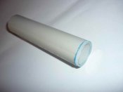
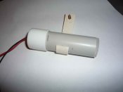
The enclosure is a 80mm long piece of standard 25mm electrical conduit. The "lense" end is cut from 3mm perspex using a hole saw in a drill press. Take out the centre drill from the hole saw so you dont get a hole in the middle of your lense. Without the centre drill you need a drill press to control the hole saw and clamp the perspex down as well to stop it moving. The other end is a 25mm chair tip with a small hole drilled for the wires to exit. The perspex 'lense" is glued on with either PVC cement (plumbers glue), or super glue. I used both and didnt notice much difference. Neither glue failed. The "bracket" was made by slicing 90mm storm water pipe into strips and using a heat gun to flatten the plastic and bend the plastic into a J shape. It was glued on with more PVC cement.
My strobes were under cover, but if exposed to weather I would recommend a drop of silicone to seal the hole where the wires exit through the chair tip. Depending on how straight the PVC is cut, a smear of silicone around the edge of the clear end would also be useful to ensure that no water gets in.

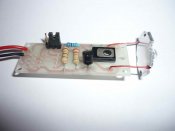
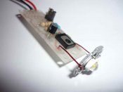
The LED is a 3W luxeon/star type LED from Aliexpress. The LED driver circuit consists of a current limiter and is based on circuits is found on the various Xmas lights forums (see ACL Strobes), with a few customisations to suit my needs - although I never used them. The unit shown is a "dumb" unit and was turned on and off via vixen. I did allow provision for a PIC to be fitted on the PCB for a true strobe effect but never bothered to fit the PICs and used vixen instead.

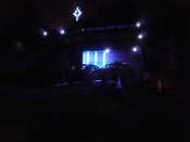
The last image shows the strobes in operation.

NOTE (very important) there is no heat sink for the LED. The strobe is fine for imtermittent operation, but if it were run continuously, or with a high duty cycle a heat sink is needed. This design doesn't provide for a heat sink. The 3W LED gets quite hot in continuous operation and I did melt one when I left it on accidentally. :(
 

Attachments

  • LED Strobe 001r.JPG
    LED Strobe 001r.JPG
    197.8 KB · Views: 267
  • LED Strobe 002r.JPG
    LED Strobe 002r.JPG
    185.8 KB · Views: 196
  • LED Strobe 003r.JPG
    LED Strobe 003r.JPG
    158 KB · Views: 138
  • LED Strobe 005r.JPG
    LED Strobe 005r.JPG
    242.3 KB · Views: 149
  • Christmas Lights 2011 052r.JPG
    Christmas Lights 2011 052r.JPG
    190.8 KB · Views: 296

Bird

LOR user
Joined
Nov 8, 2011
Messages
1,746
Location
Cincinnati, Ohio, USA
8.gif

Very nice idea. Thank you for the how to.
That's what make this site so nice is all the sharing of ideas and how to do display elements.
 

AAH

I love blinky lights :)
Community project designer
Joined
Dec 27, 2010
Messages
4,188
Location
Eaglehawk
I'm not sure what the ACL strobe pulse length is or other strobe lengths are when controlling strobes via dmx with blinky software the limitations of the dmx standard affect the minimum pulse time (and interval) which is about 1/44th of a second. I'm not sure if this makes much difference to the appearance of the strobes as some electronic strobes are capable of pulse times in the 1/1000th of a second range.
 

damo1271

Full time elf
Joined
Oct 12, 2011
Messages
202
Location
Adelaide
In theory you could trigger the strobe using DMX and then use the strobe internal SW to set its own pulse length and be completely independent of the DMX, other than the initial turn on. But whatever pulse length you set, you would be limited to it, ie DMX would only ever turn the strobe on. The strobe SW would turn itself off at the end of the defined pulse(s).
I have attached a waveform diagram to try and show what I mean.
My modified ACL SW (that I didnt end up using) senses the on signal from my renard controller and then flashes the strobe for about 1 second from memory, at 3 or 4hz, irrespective of whether the renard signal is still on or off.
 

Attachments

  • strobe waveform.jpg
    strobe waveform.jpg
    37.8 KB · Views: 96
G

GoofyGuy

Guest
damo1271 said:
In theory you could trigger the strobe using DMX and then use the strobe internal SW to set its own pulse length and be completely independent of the DMX, other than the initial turn on. But whatever pulse length you set, you would be limited to it, ie DMX would only ever turn the strobe on. The strobe SW would turn itself off at the end of the defined pulse(s).
I have attached a waveform diagram to try and show what I mean.
My modified ACL SW (that I didnt end up using) senses the on signal from my renard controller and then flashes the strobe for about 1 second from memory, at 3 or 4hz, irrespective of whether the renard signal is still on or off.

So if Im understanding you would send just an on signal, the onboard chip/memory will determin the frequency of the strobe. I like it as DMX doesnt have the speed I would be looking for.
 

fasteddy

I have C.L.A.P
Global moderator
Joined
Apr 26, 2010
Messages
6,648
Location
Albion Park NSW
These babies must be very bright as I found the 1 watt LED strobes i built were more than enough for a great effect. In fact there may just be a group buy announcement soon on the ACL strobes
 

joelrose

NW Iowa
Joined
Jul 3, 2010
Messages
41
Location
NW Iowa
Can I buy a vowel on some of those parts.
Is it just an LM317 with a resistor being used?
Since you only have two wires there must be a few extra parts there.
I know you mentioned the pic was not being used.
So what exactly is the driver circuit there?

Joel
 

damo1271

Full time elf
Joined
Oct 12, 2011
Messages
202
Location
Adelaide
I have attached the schematic of the strobe and the PCB layout. This also has the part nos. Note that if the BD139 is used (which I used) it is inserted "upside down".
I cant take much credit for the schematic. Is is based on the ACL strobe and a constant current driver circuit and I simply modified it for my needs.
I ran it from 12V (DC) supply since I didnt use the PIC. If you use the PIC, you can run from 5V DC.
Without the PIC, bridge pins 2 and 3 on JP2. (I soldered in a wire) The Strobe is on when the power is on.
If using the PIC, bridge pins 1 and 2. When the power turns on the PIC triggers the strobe based on the PIC program. It would be possible to modify the PIC code to add a trigger wire, but this, for me was just another wire in the system!

5V DC is connected to VCC and GND. I soldered the wires directly to the board since on my PCB design I didnt provide for any form of connector to keep the profile low.

The current is set by R3 and R4. I allowed for 1/2W resistors in parallel to deal with the power dissipation. 3W LED was around 700mA giving Rtotal (R3//R4) =1 Ohm. I used R3 = 1.8R and R4 = 2.2R to give 1 Ohm in parallel. Note that this runs the LED at its maximum rating. Since they were on in short bursts this was OK for me, and given the total cost of the strobe was about $3 I wasnt too fussed if one went pop!

I have posted the PIC code, again it was taken from a Xmas light forum (DoityourselfChristmas) and I modified it for what I was planning at the time. It kind of flashes like a pace car strobe (3 quick flashes). Credit for the code belongs to the original writer. The code describes all the other jumper settings/options.

To answer an earlier post, using a 3W LED they were quite bright. You certainly couldnt look at them directly :eek: ! I hadnt seen the brightness of these before and figured since the 3w were the same price as the 1W LEDs why not go 3W.
 

Attachments

  • Const Current LED driver_PIC SCH.pdf
    18.8 KB · Views: 135
  • Const Current LED driver_PIC PCB.pdf
    19.3 KB · Views: 96
  • Copy of ledstrobe-f.txt
    10.8 KB · Views: 81

damo1271

Full time elf
Joined
Oct 12, 2011
Messages
202
Location
Adelaide
GoofyGuy said:
So if Im understanding you would send just an on signal, the onboard chip/memory will determine the frequency of the strobe. I like it as DMX doesnt have the speed I would be looking for.

Yes that is correct. The strobe I made will turn on when power is applied and do its thing for as long as power is applied, but it could be modified with a trigger instead. Given you want flashes shorter than DMX can provide, then setting the strobe to flash once and then stop shouldn't be a problem.
The code I posted would be very inefficient for what you want to do, particularly for a one off flash in a millisecond pulse length.
 

chrysanthy

New elf
Joined
Mar 27, 2012
Messages
2
Great design and it looks operate well. thanks for the note part. In terms of life span heat sink is necessary. ;)
 

jeffrae

Apprentice elf
Joined
Jun 2, 2010
Messages
62
Location
Linville
You could use the dmx value to set the length and the frequency of the strobe
though a preset range of options..

regards Jeff
 

sucyyuan

New elf
Joined
Nov 13, 2012
Messages
4
Wow, I saw your discussion really learned a lot of knowledge, this is really is a great idea
 
Top