ECG-P2-1

Rxsd

New elf
Joined
Dec 22, 2014
Messages
12
Hi guys
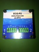
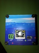
Just received my ECG-P2-1 controller, this is the card only and does not have the v+ 0r v- marked for power input.
Also the outputs to the pixels are not marked ground, power ,clock or data.
Is there a drawing to show these inputs and outputs on this forum, help needed.
Thanks for your time, I'm sure I will get the hang of all this in due time, new member.

Cheers
Ray :)
 
The P2 is the same rear panel as the D2. The case is shown here in the wiki with the polarity marked (-ve near board edge and +ve near RJ45).
 
Thanks for that .
Now have a starting point

Ray :)
 
Rxsd (Ray) hope these photos help
image.jpg image.jpg


Mararunr, I got mine by following the process below (copied from the joshua1sys website)
"Orders should include product requested, quantity, shipping mode, and complete shipping address. Orders should be placed via email to: j1sales@joshua1systems.com
We reply via email with an invoice for confirmation and payment."
 
David_AVD said:
I've just added trimmed versions of those pics to the ECG-P2 wiki page.

Many Thanks to David for the add to Wiki!!! :)

Every little bit of info brought out on things can only help all those who are getting started with this stuff.

As an added for the Wiki, you could include the test pattern that runs on the P2 as well.

The first port can do 4 universes so the test pattern is set for 1 white, 2 white on pixel 171, 3 white on pixel 341, 4 white on pixel 511. The second port then starts with universe 5 so it does 5 whites.

It rotates R G B on the strings and then walks 1-8 whites down the strings.

I am not sure on the test patterns used on the newer nECG-DP2 but I sent Ed an email to ask him about it.
 
Back
Top