I’m just going to preface this by saying that I thought I knew what I was doing, but I quite apparently don’t. Since I don’t feel like starting a fire (I think I almost have at least twice now), I really want to know what I am doing wrong, and what I’ve already destroyed and need to replace.
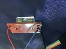
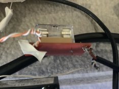
Ok, so I’ve got a 12v 30A Alitovo power supply from Amazon, a bunch of 12v WS2811 pixels, a raspberry pi 4, and some custom circuit boards and fuses.
The setup works perfectly fine when all 500 pixels are connected to the pi and PSU via jumper cables, with absolutely no issues.
The problems started happening after I tried to add in fuses, pigtales, and bump the 3.3v output from the pi to 5v (Which seems to be recommended by a lot of people).
Below, I’ve attached a (mediocre) drawing of my setup. The second image is the same circuit diagram that it embedded in the big drawing, but in readable format.
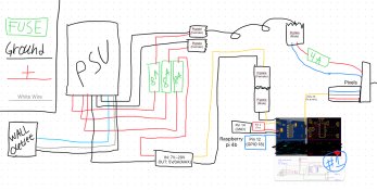

I’ve blown about 10 fuses at this point, and after the first fuse blow, only had one string connected so I did not mess the pixels up or anything. lights do one of the following every time I start it up and run a sequence over FPP.
1) Work properly. This is rare, and every time I turn the system off to add one more string, after turning it back on again it never works right. If I add all the strings (With a 4A fuse, and connection to the other pigtale halfway though the line), it ago does not work.
2) Blow a fuse somewhere. The 8A fuse on the pigtale that does from the PSU to the lights is the most common one, but the 4A fuse at the lights themselves did blow once.
3) Do absolutely nothing at all
- - -
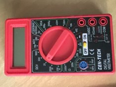
So I pulled out a multimeter to try and figure out if a wire was not connected right, if something was backwards, not throwing enough power, etc.
I tried a bunch of things, but here are the ones I remember:
1) Set it to “20DCV” and went from Pin 18 on the pi to the data in on the pixels, while the pixels were powered as shown in the diagram. No fuses exploded, the lights did not work, and the reading was well under 1V. I bypassed by custom circuit board for this. Since I thought the reading was supposed to be around 3.3, I tried a different pi I had lying around connected to the circuit as shown above. Don’t recall what happened, but the lights did not work right. Testing it the same was as described above, it also read well under 3.3. Connecting it to the custom circuit board and testing the output did not change the reading. At this point, I re-soldered the custom circuit board with a new board and all new parts, did not resolve it.
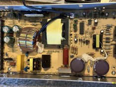
2) After this I quit, but i thought the PSU might be an issue, so I unplugged the pi and the pixels (But left the cables and fuses plugged into the PSU), set the meter to “20VDC”, and touched the black lead to “V-“, and the red to “V+” on the PSU. I swear I did this before with no consequences, but this time something popped and a bunch of smoke came out of the PSU. It shut off, then restarted itself and appeared to run fine (But I did not plug anything into it to actually test that theory). Someone I talked to said I probably blew a capacitor in the unit, so assuming they are right, is it still safe and reliable to use? For the record, the 2 of the 3 8A fuses connected to the unit blew out as well.
summary:
I’m an idiot and know significantly less then I thought, and really need help figuring out what the heck went wrong and how to fix it as this project is taking both too much time and too much space (Let alone all the frustration).
If you have any ideas / thoughts as to what went wrong or how to fix it, they would be greatly appreciated!
Ok, so I’ve got a 12v 30A Alitovo power supply from Amazon, a bunch of 12v WS2811 pixels, a raspberry pi 4, and some custom circuit boards and fuses.
The setup works perfectly fine when all 500 pixels are connected to the pi and PSU via jumper cables, with absolutely no issues.
The problems started happening after I tried to add in fuses, pigtales, and bump the 3.3v output from the pi to 5v (Which seems to be recommended by a lot of people).
Below, I’ve attached a (mediocre) drawing of my setup. The second image is the same circuit diagram that it embedded in the big drawing, but in readable format.


I’ve blown about 10 fuses at this point, and after the first fuse blow, only had one string connected so I did not mess the pixels up or anything. lights do one of the following every time I start it up and run a sequence over FPP.
1) Work properly. This is rare, and every time I turn the system off to add one more string, after turning it back on again it never works right. If I add all the strings (With a 4A fuse, and connection to the other pigtale halfway though the line), it ago does not work.
2) Blow a fuse somewhere. The 8A fuse on the pigtale that does from the PSU to the lights is the most common one, but the 4A fuse at the lights themselves did blow once.
3) Do absolutely nothing at all
- - -
So I pulled out a multimeter to try and figure out if a wire was not connected right, if something was backwards, not throwing enough power, etc.
I tried a bunch of things, but here are the ones I remember:
1) Set it to “20DCV” and went from Pin 18 on the pi to the data in on the pixels, while the pixels were powered as shown in the diagram. No fuses exploded, the lights did not work, and the reading was well under 1V. I bypassed by custom circuit board for this. Since I thought the reading was supposed to be around 3.3, I tried a different pi I had lying around connected to the circuit as shown above. Don’t recall what happened, but the lights did not work right. Testing it the same was as described above, it also read well under 3.3. Connecting it to the custom circuit board and testing the output did not change the reading. At this point, I re-soldered the custom circuit board with a new board and all new parts, did not resolve it.
2) After this I quit, but i thought the PSU might be an issue, so I unplugged the pi and the pixels (But left the cables and fuses plugged into the PSU), set the meter to “20VDC”, and touched the black lead to “V-“, and the red to “V+” on the PSU. I swear I did this before with no consequences, but this time something popped and a bunch of smoke came out of the PSU. It shut off, then restarted itself and appeared to run fine (But I did not plug anything into it to actually test that theory). Someone I talked to said I probably blew a capacitor in the unit, so assuming they are right, is it still safe and reliable to use? For the record, the 2 of the 3 8A fuses connected to the unit blew out as well.
summary:
I’m an idiot and know significantly less then I thought, and really need help figuring out what the heck went wrong and how to fix it as this project is taking both too much time and too much space (Let alone all the frustration).
If you have any ideas / thoughts as to what went wrong or how to fix it, they would be greatly appreciated!


