Falcon F3 or F4 board pictures please?

OldMarty

New elf
Joined
Dec 27, 2016
Messages
38
Location
Melbourne, East Suburbs
Hi All,

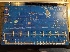
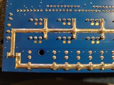
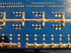
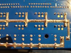
If anyone has a Falcon (V3 or V4) controller board laying around, can you please take some close-up photos of the underside of the board for me? mainly around the pixel output connectors.

Thanks in advance.
Marty
 

Indigogyre

Journeyman Elf
Generous elf
Joined
Jun 26, 2021
Messages
424
Hello,

I was actually working on one when I read this. Hope these helps.


Dean
 

Attachments

  • F16v4Back.jpg
    F16v4Back.jpg
    1.2 MB · Views: 12
  • F16v4Back1.jpg
    F16v4Back1.jpg
    616.2 KB · Views: 12
  • F16v4Back2.jpg
    F16v4Back2.jpg
    635.7 KB · Views: 11
  • F16v4Back3.jpg
    F16v4Back3.jpg
    645.2 KB · Views: 12

OldMarty

New elf
Joined
Dec 27, 2016
Messages
38
Location
Melbourne, East Suburbs
Hello,

I was actually working on one when I read this. Hope these helps.


Dean
Hi Dean,

Thanks so much for doing that, greatly appreciated.

Is the heavy solder (soder) on the main power tracks something that you've added yourself? or is that standard "out of the box"?

Also, do you know if the data pins on each pixel output connector are simply all bussed together and being driven by one data-driver chip? or is each pixel output data driven by it's own data-driver chip? (16 driver chips).

I guess if you multimeter those little bare gold pads between 2 or more pixel output connectors, that will confirm that they're all bussed together (or not).

Thanks in advance.
 

Indigogyre

Journeyman Elf
Generous elf
Joined
Jun 26, 2021
Messages
424
Everything is stock out of the box. I've since mounted the board into a controller box and currently do not have access to the back of it for the time being.
 

David_AVD

Grandpa Elf
Community project designer
Generous elf
Joined
Jun 12, 2010
Messages
4,682
Location
Victoria Point (Brisbane)
Pixel controllers all have separate data lines from the micro / CPLD / etc to each output port. This is often via a logic buffer IC and series resistors to limit the slew rate a little.
 

OldMarty

New elf
Joined
Dec 27, 2016
Messages
38
Location
Melbourne, East Suburbs
Pixel controllers all have separate data lines from the micro / CPLD / etc to each output port. This is often via a logic buffer IC and series resistors to limit the slew rate a little.
Thanks David,

Yeh, i wasn't quite sure if there were 16 different data streams to independently control each pixel string.

I guess this way makes sense to send unique data to each of the 16 pixel strings compared to just 1 buffered stream feeding all 16 pixel strings.

Thanks for confirming.
 

djgra79

My name is Graham & I love flashing lights!
Global moderator
Generous elf
Joined
Dec 27, 2011
Messages
2,163
Location
Cranbourne West
May I ask why you are asking? Is your board not performing as it should or requires repair?
 
Top