Flickering lights when extending the data signal on WS2811

orchidman33

Full time elf
Joined
Jan 14, 2019
Messages
116
I have been waching this thread with interest.
Question, - if you are using 12V strip is your power supply 12V Dc or 5V as per your labeled photo.
Question/ observation. You are using a linking cable between strips that has Black, Green/yellow and then another Black,. Have you Checked that you have not accidently crossed the two black wires at one end.

As for using data cable (use patch leads or Stranded cable, NOT solid core) , I am using Patch leads here 3 cores for V+, 4 cores for 0V and one for data. running a 5m 12V strip @ 30LED or 10 drivers per meter at 20% brilliance I am going 15+ meters from the power supply, no problem.

I also think that your programed pattern will not display as you want. This is due to your display is like having 4 x 2 meter strips side by side -NOT just one straight line .

Hope this gives some ideals to your issue.
 

whatthej

New elf
Joined
Dec 31, 2019
Messages
42
Good pickup Orchid, I mislabelled; it's a 12V power supply. Linking cable tested and not cross wired
I'm perplexed by the data issues because others have gotten away with much less. I don't know if the ES Pixel Stick firmware takes some shortcuts with the PWM signal that makes it more susceptible to signal degradation. I'm using stranded cable for the data pins but I'm not sure why that matters (it's just flexibility) but I've also tried it with patch leads with no success (it's worse than the 1.5mm cable). What's your wiring setup when using patch leads - do you use the same twisted cores, and which twisted pair does the data share?

I actually wonder if I'm making some grounding problems because my 2nd strip is closest to the power, but I keep thinking that surely that can't be it because otherwise power injection from both ends won't work
 

orchidman33

Full time elf
Joined
Jan 14, 2019
Messages
116
Looking at your connections. I do not use any of the strip connectors, Do data techs/ use strip connectors to join thier patch leads ! For data connections its best practise to use what the data techs use but all my joints are soldered. Stranded data data cablehas the ability to carry more current due to the number of cores (more surface area).
When I make my leads using patch leads , core blue,blue/white,brown,brown white are 0V, cores orange,orange/white, green/white are +V and green is the data.

A grounding fault maybe, but I was thinking possibly a +V fault and the induced voltage, when large enough and the light was instrucked to turn on, the light would flicker. But I keep coming back to a wiring fault.I was also thinking that you may have accidently bridged 0V to data when you have extended the data line.
 

BAZMick

Full time elf
Generous elf
Joined
Nov 26, 2019
Messages
484
I am starting to think a GND issue. You're only bringing the data down from the top of the strip but no GND. Also check your voltage after the first strip.
I also agree with Orchidman33, I use those bootlace ferrules in my wiring a lot but never on data; it's always soldered or pigtail connections.
 

Srmorgan

Full time elf
Joined
Jan 26, 2020
Messages
100
I forget what the name is but on my esp8266/32’s they only have a 3.3v data signal so I had to step the voltage up to 5v on all but 1 because it was right next to the string. The rest flickered like crazy till I fixed that. I’ve never used a wemos do not sure what their voltage is.
 

whatthej

New elf
Joined
Dec 31, 2019
Messages
42
@Srmorgan The Wemos is based off an ESP8266 chip, so you might be on the money here. Although, I'm wired from the chip straight into the LED strip and I would've thought that past the first node, the WS2811 chip would resample everything back to 5V. (Because if it doesn't, then why is the distance between nodes the most important, rather than the distance from the source signal?)

How did you step up your voltage for the data signal and still handle the 800kHz? How were the others (that were flickering like crazy) wired up to the controller, was it like mine (Dout of first strip to Din of second strip) or separate pins (multiple Douts from the ESP chip)?

Edit: based on your suggestions, my googling has come across this!
View: https://www.reddit.com/r/arduino/comments/56clv9/io_voltage_on_wemos_d1_and_d1_mini/
Might be my issue here; trip to altronics tomorrow once I hear back on how you stepped up!
 
Last edited:

Srmorgan

Full time elf
Joined
Jan 26, 2020
Messages
100
My phone is on the Fritz and won’t let me look at the link. But I used a logic level shifter to bump up the data signal. The way it was explained to me is that if the data wire is short enough the 3.3v is high enough to be read by the first pixel and then converted after that. But if the wire is to long voltage drop has its way with it then the rise of the signal does not go high enough to be read as a 1 properly and then you get all the crazy flickering. I’ll post the level shifter I used when I get home. I got mine from Amazon. Three of my year round esp’s are in a control box outside so I stuck one level shifter in there and it is able to boost the signal of 4 devices. My level shifter has 6 gpio pins on both side. The two middle ones are for the v- and a reference 3.3v v+. The opposite ones are the 5v counterparts. Then I used those wires used for gpio pins(i don’t know the name) to pass the signal from the esp to the level shifter on the 3.3v side then I soldered another gpio wire to a twisted pair and made the connection to my first pixel. Works like a charm.

sorry but I’m not sure what a dout is. But my esp’s are the controllers for my permanent lights. I installed wled on them and control them remotely. I think it’s pin 4 on the 8266 and pin 2 on the 32. I don’t remember off hand. And I connect those straight to the lights. (With the level shifter in between). Then for my Christmas show I don’t want to trust the wireless too not mess it up so I made some pigtails with some cat5 cable using v- and data only then attached the gpio wires with a male end and used it just like a gpio pin. Then pulled the wires off of the ESP and attached it to the cat5 pigtail so my falcon controller/FPP can control the string. Then I can just switch them back after Christmas.
 
Last edited:

Srmorgan

Full time elf
Joined
Jan 26, 2020
Messages
100
These are the level shifters that I used. They are small but effective. Unfortunately they show to be out of stock. I know there are others. It seam like adafruit makes one If I remember correctly. there was also something To do with how fast they are. I dont remember how to tell off hand but if I find it later I will let you know.


and I seem to remember reading that same article while I was figuring out my flickering problem. Good luck.
 

TerryK

Retired Elf
Joined
Feb 9, 2020
Messages
655
Location
West Central Ohio
This thread has grown quite a bit the last day or two. Nothing earth shattering in any of your answers to questions from anyone. I do not think it matters much but I think I would replace the JST connectors. The larger xConnect, Ray Wu, or Paul Zhang connectors will work of course but for something smaller you might consider these:
I use the small 2 pin because I keep the data and power separate. Wires are a bit small so if used for power I would keep them as short as practical to minimize voltage drop. My reasoning for the replacement is the circular connectors have a little less IR drop across the socket to pin and are environmentally protected better.

No one has asked but I was wondering how hard you drive the strips. You've also indicated that there is little voltage drop but did not indicate how hard the strip was being driven when you made the measurement. The WS2811 strip you have is of a resistor type and I do not have, have not used such so I have no data pertaining to voltage drop versus drive levels. From a loose comparison to a WS2815 strip I've tested, I would expect at 100% white to see approximately a 2.5 volt drop at the end of a strip.

Levels converters from 3.3 to 5 have been mentioned and as they are fairly common with small board processors; RPis, BBBs, PICS, etc. should be easily obtained. Just note that they come in either or both directions and various qualities. World Semi's WS2811 Datasheet indicates the IC has an internal reshaping circuit so if you can get the first and second pixels to work correctly, the other should also. A concern with driving a WS2811 with a 3.3 volt controller signal is what are the controllers output drive levels and where is the WS2811's input window. World Semi says the data in should be between .3VDD and .7VDD. For a 5 volt and a 12 regulated IC that is 1.5 to 3.5 volt (regulated WS2811s have a 5 volt regulator so pixel sees 12V, IC sees 5V). For a resistor pixel however, Absolute Maximum Rating for VDD is speced at 6.0 to 7.0 Volt and a resistor is used to get the 12 Volt down 'hopefully' 'somewhere' in that range. What does that make the input voltage window? A bit difficult to say.

A note regarding wire ferrules. I have used, seen used ferrules on everything for the most part from 28 AWG to 6 AWG; both quad and hex crimpers. In a pinch I've used pliers (duo crimp?). Tightened properly a screw terminal will further crush the ferrule to 'mush' the strands and ferrule interior. What one needs to avoid is the use of a wire ferrule in a cage clamp terminal (Wago is fairly popular, patented the design I think).

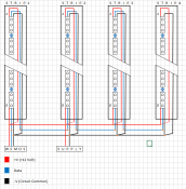
Back to the problem at hand, whatthej, if you are willing to try an experiment I would like you to try the following.

Wire/re-wire the strips as shown
1608263433291.png
Program the controller to go 100% white on strip 1 only, all other strips/pixel completely off. If it works, with the strip 1 pixels still on measure the voltage to Strip 1 Point A +V to -V. Turn strip 1 all off and try the same thing with Strip2, then 3, and then 4.
If strip 1 cannot be illuminated, disconnect the +, data, and - at point A (which feeds #2) and troubleshoot Strip 1.

Note I changed the wire arrangement slightly. In your photo the supply goes through the Wemos enclosure, I show it to the terminals. May matter, may not; making sure Wemos enclosure wiring connections are not a problem. Don't think I messed up in the diagram but...
 

whatthej

New elf
Joined
Dec 31, 2019
Messages
42
Thanks all for your input; I certainly want to get this resolved but in the interim have used more controllers to get me through this season. Will revisit this in mid Jan for sure! @TerryK Thanks for doing the superb diagramming and @Srmorgan and @BAZMick for digging up the logic level converter details
 

TerryK

Retired Elf
Joined
Feb 9, 2020
Messages
655
Location
West Central Ohio
You are welcome. The thread can archive for some time and be reserected when you are ready. A parting question; mentioned in a previous post (#15 ?) were similar setups that worked (almost). I'm wondering if a slightly different physical arrangment is bringing a hidden problem to the foreground. Cheers.
 
Top