Hey all,
I recently obtained from a forum member, a Raspberry Pi Compute Module 4, as well as an MCUZone Carrier board.
For me, the use case was to run FPP and drive some Colorlight cards for a panel, so having the 1G port for the colorlight interface and the 100M for show network was perfect.
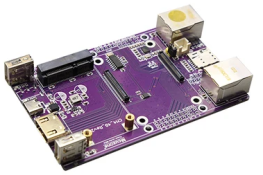
This carrier board has 2x USB2 Type A's, a USB C, two ethernet (1x 1G, and 1x 100M) and a M2 slot & SIM slot for a 4G Card. It also has an SD card slot (not usable, more on this later)
It took a little bit of trickery to get going, so this is a little tutorial on what I did in the hopes that it's useful for anyone else attempting the same build.
This is the carrier board:

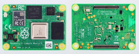
And this is the CM4:

The CM4 specs follow the Raspberry Pi 4, including wifi capability, and my particular board is a 2GB RAM model. It has one added feature, which is the inclusion of 32GB of onboard eMMC. This is perfect for running FPP on.
This is why the SD Slot doesn't work on the carrier board, the pins for the storage are not wired to the bus underneath. You need to use the CM4-Lite which does not contain the eMMC if you want to use the SD Slot.
So this makes it a bit more fun to load FPP on initially. This involves putting a bootloader on so that the eMMC appears as a memory stick to your host PC and then loading on the image. This is covered in the first steps below.
Another interesting fact is that the CM4 only has one USB interface internally. This connects to both the USB-C for device/OTG mode, and to a USB hub in Host mode. However only one mode can be active at once, and USB Host Mode is NOT active by default- which means neither the 100Mb ethernet nor the USB slots work out of the box. By default it's in OTG device mode. So more tinkering there, and covered in the second lot of steps.
Installing FPP to the CM4 eMMC
Here are the steps. My links are to the Windows versions of the software, but you can use MacOS or Linux if either of those are your flavour of choice.
If, like me, you intend to use the Gig port for a Colorlight, we wait until everything is ready to go before changing network settings because otherwise we're doubling up for no benefit.
Configuring FPP for USB to work - This is only requiredfor FPP v7 and earlier. FPP v8 and later appear not to need this (see note below from @Kent)
https://auschristmaslighting.com/th...cuzone-cm4-4g-carrier-board.16091/post-142592

With that, you're all done and checked. FPP is installed, the USB ports are working, the second ethernet device is working.
You can now configure the rest of FPP to your hearts' content!
Now, if you do an FPP OS upgrade, I'm not sure if it will blow away the config.txt changes. So that will be an interesting one to try down the track.
Hope this helps someone who is in the same boat I was figuring this out.
Feel free to reach out or post in here if there are any questions
I recently obtained from a forum member, a Raspberry Pi Compute Module 4, as well as an MCUZone Carrier board.
For me, the use case was to run FPP and drive some Colorlight cards for a panel, so having the 1G port for the colorlight interface and the 100M for show network was perfect.
This carrier board has 2x USB2 Type A's, a USB C, two ethernet (1x 1G, and 1x 100M) and a M2 slot & SIM slot for a 4G Card. It also has an SD card slot (not usable, more on this later)
It took a little bit of trickery to get going, so this is a little tutorial on what I did in the hopes that it's useful for anyone else attempting the same build.
This is the carrier board:

And this is the CM4:

The CM4 specs follow the Raspberry Pi 4, including wifi capability, and my particular board is a 2GB RAM model. It has one added feature, which is the inclusion of 32GB of onboard eMMC. This is perfect for running FPP on.
This is why the SD Slot doesn't work on the carrier board, the pins for the storage are not wired to the bus underneath. You need to use the CM4-Lite which does not contain the eMMC if you want to use the SD Slot.
So this makes it a bit more fun to load FPP on initially. This involves putting a bootloader on so that the eMMC appears as a memory stick to your host PC and then loading on the image. This is covered in the first steps below.
Another interesting fact is that the CM4 only has one USB interface internally. This connects to both the USB-C for device/OTG mode, and to a USB hub in Host mode. However only one mode can be active at once, and USB Host Mode is NOT active by default- which means neither the 100Mb ethernet nor the USB slots work out of the box. By default it's in OTG device mode. So more tinkering there, and covered in the second lot of steps.
Installing FPP to the CM4 eMMC
Here are the steps. My links are to the Windows versions of the software, but you can use MacOS or Linux if either of those are your flavour of choice.
- Obtain a copy of Raspberry Pi Imager, if you don't already have it from https://downloads.raspberrypi.org/imager/imager_latest.exe
- Obtain a copy of rpi-boot from https://github.com/raspberrypi/usbboot/raw/master/win32/rpiboot_setup.exe
- Assemble the CM4 onto the carrier board. This may mean using spacers and screws if you're going to attach the supplied heatsink, which is recommended for a Pi-4 due to its heat output.
- Between the CM4 and the ethernet jacks is a header labelled BOOT. You need to install a jumper cap to connect the pins.
- Connect the carrier boards' USB-C connector to your computer with an appropriate cable. Two red lights and a green light will illuminate.
- Run the rpi-boot application. This will present a console window which will show it loading on a bootloader. It will then close and disappear.
- Shortly after this, your PC will detect another drive attached and may prompt you to format it. Ignore this and press no.
- Load up Raspberry Pi imager application
- Just like if setting up an SD card, click the Choose OS button, find Other Specific-purpose OS, select Falcon Player (FPP), and then choose FPP v7.5 Pi
- Now choose Select Storage and find the CM4 eMMC device that appears
- Press Next. This will write out the eMMC and then validate it.
- Once this is complete, disconnect the carrier board from your USB port on the computer, and remove the jumper cap on the BOOT pins you installed in Step 4.
If, like me, you intend to use the Gig port for a Colorlight, we wait until everything is ready to go before changing network settings because otherwise we're doubling up for no benefit.
Configuring FPP for USB to work - This is only requiredfor FPP v7 and earlier. FPP v8 and later appear not to need this (see note below from @Kent)
https://auschristmaslighting.com/th...cuzone-cm4-4g-carrier-board.16091/post-142592
- Look at the carrier board, end on, with the ethernet jacks facing towards you. The gigabit port is on the left, and the 100Mbps port is on the right.
- Connect the gigabit port to your router/switch at home which has DHCP running on it. I find this so much easier than any of the tether options. That being said, whilst it should work using the Wifi Tether, I didn't test it.
- Power on the carrier board & CM4. Do this over the USB-C socket, however, use an EXTERNAL power supply, not a USB Interface to your laptop. This bit me for a while. Firstly, the CM4 board might pull too much power for your USB port on the PC to handle, but secondly, and more importantly, despite config changes, the CM4 WILL stay in OTG/Device mode and switching it to Host mode is impossible.
- Watch for FPP to boot, the green light will blink on eMMC access. Once it slows down from being crazy fast, it's mostly initialised and you should be able to load up the web interface
- Browse to http://fpp.local/ from a computer on the same segment, and you'll be greeted with the FPP initial setup screen.
- Go through the initial setup, hostnames, timezones, location, sharing etc, as required.
- Extend the storage when prompted to cover the full 32GB eMMC rather than the default.
- As mentioned, don't set any network settings at this point. Give it a reboot for the storage to take effect.
- Once it powers back up, log in using SSH. This can be done from a Windows/Mac/Linux command prompt by typing
, subsituting fpp.local for the hostname if you changed it.Code:
ssh fpp@fpp.local - Use the default password of falcon unless you explicitly changed it as part of setup.
- Now, we need to edit the RPI configuration file, stored in /boot/config.txt - run
to bring it up in the nano text editor.Code:
sudo nano /boot/config.txt - Find a section called
and in that section there is an optionCode:
[cm4]- You will want to comment this out by adding a # at the start of the lineCode:otg_mode=1Code:#otg_mode=1 - Now, scroll futher down and find an option that says
- This needs to be modified to include additional data on the end -Code:
dtoverlay=dwc2Code:dtoverlay=dwc2,dr_mode=host - Once this has been modified, Save the file by typing Ctrl-O and hitting Enter. You can then exit nano by typing Ctrl-X.
- Finally, shut down the CM4 by typing
Code:
sudo halt - Once the device has shut down, unplug the power for 3 seconds, and power the CM4 back on.
- Thats it - once it boots back up, we can then validate
- Log into FPP web interface
- Go to FPP - Help -> Troubleshooting Commands
- Click on USB Device Tree
- This should show a tree of devices that looks like this:

- If it only shows the top Class=root_hub then it's not working. But if you see a bunch of devices, specifically the 'Communications' class, then you're looking good. In my case, I also see the Class=Mass Storage as I had a USB Stick connected as well.
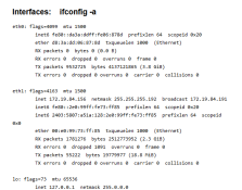
- Now scroll to the top of the window and click on Interfaces
- You should also see both eth0 (gigabit) and eth1 (100mbit) appearing

With that, you're all done and checked. FPP is installed, the USB ports are working, the second ethernet device is working.
You can now configure the rest of FPP to your hearts' content!
Now, if you do an FPP OS upgrade, I'm not sure if it will blow away the config.txt changes. So that will be an interesting one to try down the track.
Hope this helps someone who is in the same boat I was figuring this out.
Feel free to reach out or post in here if there are any questions
Last edited:

