Hmmm, Power..... Not...

Binkles

Full time elf
Joined
Dec 11, 2012
Messages
263
Location
Baldivis
575_powergrid.jpg


As you can tell, I'm an artist, and photoshop is just a breeze for me :)

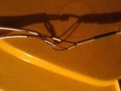
Anyways, the red lines are V the black lines are G, orange is data.

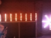
Top picture, feed power - all work though of course the power getting low in the middle (will attach a picture shortly).

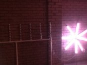
Bottom picture, there is 3 feeds of power, one at the start, one in the middle, and one at the end. But then I get bright star, and fugged waterfall (will attach picture).

The three power feeds are coming from an old computer psu. They each have different black and red lines from the psu.

The pixels are 5v and there are 144 of them.

With the PSU I can connect 170 12v strip/modules with a feed at the start, and one at the end as well as the 144 pixels.

Suggestions?

I'll also post the connector that I'm using.
 

Binkles

Full time elf
Joined
Dec 11, 2012
Messages
263
Location
Baldivis
First pic, power at both ends.

Second pic, power at start, between star and waterfall.

3rd pic, wiring. Left of the pic going to waterfall, right of pic is the power, and the data, I've ensured that the data feed enters via the correct plug.

Mice have been trained well. When two played up and electrocuted themselves, the others learnt pretty quick....
 

Attachments

  • ImageUploadedByTapatalk HD1363179334.107732.jpg
    ImageUploadedByTapatalk HD1363179334.107732.jpg
    69.8 KB · Views: 29
  • ImageUploadedByTapatalk HD1363179499.527643.jpg
    ImageUploadedByTapatalk HD1363179499.527643.jpg
    65.8 KB · Views: 25
  • ImageUploadedByTapatalk HD1363179547.498005.jpg
    ImageUploadedByTapatalk HD1363179547.498005.jpg
    68.4 KB · Views: 29

fasteddy

I have C.L.A.P
Global moderator
Joined
Apr 26, 2010
Messages
6,648
Location
Albion Park NSW
This is caused by voltage drop, what is the cable and the length that you are using to supply power to the strips because it may be a case of too small a size cable for the current required which will cause this issue
 

Binkles

Full time elf
Joined
Dec 11, 2012
Messages
263
Location
Baldivis
I do know the one to the end is too small, though when I do a reading it says 4.98v. The problem though is trying to inject power at the half way point. As soon as I do that, I get the one faint light only on the waterfall, but the lights on the star get brighter.
 

fasteddy

I have C.L.A.P
Global moderator
Joined
Apr 26, 2010
Messages
6,648
Location
Albion Park NSW
Binkles said:
I do know the one to the end is too small, though when I do a reading it says 4.98v. The problem though is trying to inject power at the half way point. As soon as I do that, I get the one faint light only on the waterfall, but the lights on the star get brighter.

Now im confused, are you using 12vdc modules. Why are you measuring 5VDC and where are you measuring from because measuring at the power supply will always give you close to the rated voltage, its at the end of a string or strip that you need to measure to see what the voltage drop is.

A bit more info on exactly what your connecting, distances of cables, size of cables and what lights you are using
 

Bird

LOR user
Joined
Nov 8, 2011
Messages
1,746
Location
Cincinnati, Ohio, USA
It wouldn't be a simple mistake like your picture shows would it?
The middle injection power point to the waterfall has reversed polarities?
 

Binkles

Full time elf
Joined
Dec 11, 2012
Messages
263
Location
Baldivis
Bird said:
It wouldn't be a simple mistake like your picture shows would it?
The middle injection power point to the waterfall has reversed polarities?

Nicely spotted on the pic, but no reverse polarity
 

Binkles

Full time elf
Joined
Dec 11, 2012
Messages
263
Location
Baldivis
ɟɐsʇǝppʎ said:
Binkles said:
I do know the one to the end is too small, though when I do a reading it says 4.98v. The problem though is trying to inject power at the half way point. As soon as I do that, I get the one faint light only on the waterfall, but the lights on the star get brighter.

Now im confused, are you using 12vdc modules. Why are you measuring 5VDC and where are you measuring from because measuring at the power supply will always give you close to the rated voltage, its at the end of a string or strip that you need to measure to see what the voltage drop is.

A bit more info on exactly what your connecting, distances of cables, size of cables and what lights you are using

Sorry.

My p2 has the two outputs, I've set up the first as 12v, the 2nd as 5v.

Only explained the 12v to show that the psu should be able to drive all my 5v.

Will get out my ruler tonight and post distances and volts at that time.

Thanks
 

battle79

Full time elf
Joined
Dec 8, 2012
Messages
465
Location
Chirnside Park, Victoria, AU
My suggestion would be to only inject power to the waterfall side of your 'T' connection. If the star is fine then no need to inject from the end of it, just finish it's power feed at it end, and start new feed for waterfall.

Hope my rabling makes sense. And with 5V you need to use 14/0.20 cable and double up the cores for all power feeds, to stop any voltage drop issues.

Looks like your getting a good head start on next year, best of luck.

Cheers,
Rowan
 

fasteddy

I have C.L.A.P
Global moderator
Joined
Apr 26, 2010
Messages
6,648
Location
Albion Park NSW
The P2 is not designed to take that much load through it, do not connect the +v through the P2 as its only designed to take a load of 25 pixels max.

Refer to this post regarding how to connect up pixels to the P2

Now if the lights you are having issues with are 5VDC then you will require more power injection as you should inject power for every 50 pixels when using 5vdc. If using 12vdc pixels then you can inject every 100 pixels.
Battle79 has given good advice with doubling the cores for power injection
 

Binkles

Full time elf
Joined
Dec 11, 2012
Messages
263
Location
Baldivis
Man I suck at explaining.

Ok just to clarify, there is no + going to the p2, but to keep me from blowing up everything, I have all my 12v on the universes 1 to 4, and my 5v on universe 5 to 8.

I found out that the mice were behaving, the chief soldering person had major colour blindness, and is bloody lucky he has any lights left.

Somewhere along the lines, I must of stuffed up my wiring chart, and well let's just say 5 hours of resoldering to the correct chart that I, I mean the soldering person had designed, and I now have full white to both my Death Star and my waterfall.

Thanks for all the help though people, I am truly thankful to all those that gave their tips.
 

Bill Ellick

Full time elf
Joined
Dec 31, 2011
Messages
282
Location
NY
Good to hear. Trust me, we can all make mistakes so live and learn.
Nice too that you did not blow up anything. On to the sequencing !!
Just an FYI for you if you don't do this (so no bad intended either), I always adopt a color coding system for my display or anything electronic for that matter. That way I make less mistakes overall by having color coding on data, power, clock, ground, and whatever. Also makes it easier to troubleshoot if there are any problems.
 

fasteddy

I have C.L.A.P
Global moderator
Joined
Apr 26, 2010
Messages
6,648
Location
Albion Park NSW
Its always the first time that is real hard, but now you will feel a lot more confident going forward. Glad to hear that all is now good
 
Top