SarahD
Mersey Christmas Lights, maker and breaker
Hi people - apologies if this is already answered but I've been researching for a while and can find other threads with the same problem but not with a clear answer. Hoping someone can help.
I want to control two sets of LPD6803 pixels via a Raspberry Pi Zero running FPP. The lights are permanently mounted on the house, and now I'm running pixels, I want to incorporate them into the display. The controller that came with the lights was pre-programmed with 1024 choices and a remote control, but no ability to synch: https://www.aliexpress.com/i/1548109249.html. It sits in the middle of the run, and I've got 3 x 5m strips going in each direction with power injection and they've run perfectly for years.
I've bought a new real of LPD6803 so I can experiment without getting up under the eaves, and have a fresh Pi with a new FPP install. Here's what I've tried.
I've read the FPP manual, and it just says SPI can be replicated in software using the Pi pins. Good!
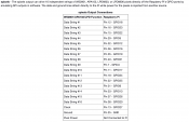
In FPP I've been into the Pi pixel string setup page and added in LPD6803 (16 lines come up, and I've just set up the first two lines. Only one is set up to GPIO pins (SPI0). I have SIP0 MOSI (GPIO 20, pin 19) -> Data in, and SPI0 Sclock (GPIO 11, pin 23) -> CI. I don't know what the Pi SPI0_CE0 pin does and it's not connected.
There's a few places where I can find these Pi GPIO pin assignments have beed tried, eg https://pinout.xyz/pinout/spi#
However, I've also found posts where these have been tried and didn't work, and were never resolved https://www.raspberrypi.org/forums/viewtopic.php?t=93447,
https://raspberrypi.stackexchange.com/questions/27440/controlling-rgb-led-strip-via-spi-and-node-js. These pins don't work for me either (noting that LPD6803 is 12V and I'm using an external 12v supply to just the strip, with 5V to the pi and grounds tied). Strip comes on blue and doesn't respond to Pi display testing. I'm clearly doing something wrong, or missing something important.
My questions are:
1) Do I need to activate SPI on the Pi, and if so how do I do that through FPP?
2) Given there's 10cm between the Pi and the LED strip, is the 3.3V likely to be the cause of the problem, or is it something else?
3) What is CE0 and do I need that connected
4) Do I need a cape/hat to make it work (and if so where please because I can't find one)
5) If none of the above, what am I missing???????
Many thanks for any words of wisdom.
I want to control two sets of LPD6803 pixels via a Raspberry Pi Zero running FPP. The lights are permanently mounted on the house, and now I'm running pixels, I want to incorporate them into the display. The controller that came with the lights was pre-programmed with 1024 choices and a remote control, but no ability to synch: https://www.aliexpress.com/i/1548109249.html. It sits in the middle of the run, and I've got 3 x 5m strips going in each direction with power injection and they've run perfectly for years.
I've bought a new real of LPD6803 so I can experiment without getting up under the eaves, and have a fresh Pi with a new FPP install. Here's what I've tried.
I've read the FPP manual, and it just says SPI can be replicated in software using the Pi pins. Good!
In FPP I've been into the Pi pixel string setup page and added in LPD6803 (16 lines come up, and I've just set up the first two lines. Only one is set up to GPIO pins (SPI0). I have SIP0 MOSI (GPIO 20, pin 19) -> Data in, and SPI0 Sclock (GPIO 11, pin 23) -> CI. I don't know what the Pi SPI0_CE0 pin does and it's not connected.
There's a few places where I can find these Pi GPIO pin assignments have beed tried, eg https://pinout.xyz/pinout/spi#
However, I've also found posts where these have been tried and didn't work, and were never resolved https://www.raspberrypi.org/forums/viewtopic.php?t=93447,
https://raspberrypi.stackexchange.com/questions/27440/controlling-rgb-led-strip-via-spi-and-node-js. These pins don't work for me either (noting that LPD6803 is 12V and I'm using an external 12v supply to just the strip, with 5V to the pi and grounds tied). Strip comes on blue and doesn't respond to Pi display testing. I'm clearly doing something wrong, or missing something important.
My questions are:
1) Do I need to activate SPI on the Pi, and if so how do I do that through FPP?
2) Given there's 10cm between the Pi and the LED strip, is the 3.3V likely to be the cause of the problem, or is it something else?
3) What is CE0 and do I need that connected
4) Do I need a cape/hat to make it work (and if so where please because I can't find one)
5) If none of the above, what am I missing???????
Many thanks for any words of wisdom.