Modify your 8 function controller to have a memory

Mike

CLAP infected!
Joined
Oct 22, 2010
Messages
280
Location
Rockingham, WA
This should go without saying it: Please do this without the controller plugged in.

This is what I have done to make some of my 8 function controllers have a memory so I don't need to reset them
every night. Its cheap to do and simple. Parts for this are available easily and should cost about $1- $1.50
It involves changing the capacitor in the controller to a larger one that holds charge longer.

You will need:
  • Soldering Iron
  • Solder
  • De soldering Braid or Sucker pen
  • 1000uf 16v Electrolytic Capacitor
  • Hacksaw
  • Duct Tape
  • 1N4148 Diode (maybe)
Note: Depending on the circuitry of your controller and the charge level of the capacitor, It may delay the start up time for the lights.
This may not be good for computer controlled lights. Sometimes up to 20 secs delay

This has worked for all my controllers , but I cant guarantee it it will work on yours. Should work on most though

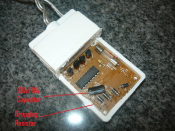
Step 1: Cut the case open With a hacksaw
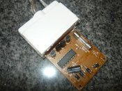
Cut the case following the lines around the controller as shown in the photo. They are glued shut.
Don't try to pry them open with a screwdriver! It will slip and stab you in the hand. Trust me it doesn't work.
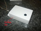
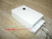
controller1.jpg

Controller2.jpg


Now flip the case onto the side without the button on it (the back side) and cut along the the line as shown
in the picture. Be careful you don't go too far and hit the board or its components
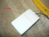
Controller3.png

Continued next post..........
 
Step 2: Pull case open
Pull the case open. It takes a little bit of force to do this as its got glue around the end. You will see the capacitor we will now desolder .Now with the board out we can get started.

Controller4.png

Controller 5.jpg


Step 3: Desolder the Capacitor
You will find a 100uf 16v capacitor that we need to desolder.Depending on the controller the capacitor
may have a 10v rating.
Either use desoldering braid or a desoldering sucker pen to do this.I used braid to do this. But its a personal
choice. Take note of the polarity of the capacitor and where it connects on the board if its not marked.

controller6.png

Step 4: Solder in the new capacitor
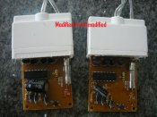
Solder in the new 1000uf 16v capacitor. Make sure you leave enough on the leads/legs to lay it down so it fits back in the
controller. Here's a picture of an unmodified vs modified

controller7.jpg

Step 5: Fit back in the box
Fit it all back in the box and you are done. Tape it up with duct tape so water doesn't get in and its good to go
Your 8 function controller should now have a memory.

If you find its not lasting the required amount of time, say 18-20 hours
You will need to solder in a small diode to stop leakage back through the circuit. Part # 1N4148.Cost about 40c for 5 of them
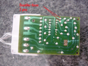
Desolder 1 side of the dropping resistor as shown in the pictures above. Now solder in the diode with the line facing towards the IC.
Now the voltage shouldn't drop too much if at all.
Normally this step isn't necessary.


I hope this helps someone out, inexperienced or experienced

Thanks
 
Further to Mikes mod.

If you do have the need for the controller to be left on the string as you plan on using the plug pack provided.

You can cut the two legs on the flat side of the transistor/FET, and desolder the third leg with the body of the device.

Then just tie the remaining legs together. This will give you permanent on state.

BIGW%20mod.jpg
 
Some other options if you want to make the memory last even longer are discussed here.

To 240V folk (Sorry if this sounds obvious) ... remember to be very careful if you ever see one of these controllers connected direct to 240V. Probably rare these days but they have been seen. 240V raises the stakes considerably when playing with this stuff... to the point of suggesting leave them alone.
 
Howdy... my first post, but won't be my last!!!

Yes, I'm a newbie and not an electronics guru, merely a lights fan...

Unfortunately like most newbies and non-electronics gurus I'm switch on A/C side, therefore needing to use the existing controllers to modify them to be static.

Big W 2010 LED's in particular (already have my older stock fine).

After wrangling with the bloody thing for a while now, looks like the circuit is as per Tabor's posted above, which is good.

2 problems/questions though:

1. Is there an easy way to get these things apart? I literally spent 20+ minutes to get the case apart. Even then it's the BOTTOM rather than the top of the circuit that is exposed. To get access to the full board from what I can see I would need to either hack through the plastic or remove the silicon.. neither of which are particularly attractive.
2. Given the above comment, would it not be possible to do this from underneath? i.e. de-solder all the legs, then solder across the connections (same effect as twisting the spare legs)?

I'm going to have to do a lot of these it would seem so it could be a killer methinks...

EDIT: Ah... looking at the first post a bit harder looks like question 1 is already answered. No there is no easy way, but the cut makes sense. Missed that first run through.... Amend that to what people find best to cut through the relatively thick plastic...

Question 2 is still interesting though. Presuming it would work as pretty much it's just a hardwire bypass.
 
In the end I used a hacksaw to make the cuts... worked pretty well (no idea if it was the right way to do it or not).

Still learning, but managed to hack 7 of them into the requisite 3 pieces (leaving behind enough shaved plastic to fill a mug), snipped the transistors, desoldered the necessary bits, twisted and soldered the other bits, pieced the jigsaws back together and using sealant and electrical tape got them looking just as neat and probably more water resistant than when they started.

More amazingly no failures out of that initial batch of seven.

Now... just 15 more to go over the next couple of days...

Thankyou so much for posting this information in the first place, it's been a HUGE help!!!
 
Glad some people are finding this useful.

Have now updated top post to include hacksaw. ;)
 
TimW said:
To 240V folk (Sorry if this sounds obvious) ... remember to be very careful if you ever see one of these controllers connected direct to 240V. Probably rare these days but they have been seen. 240V raises the stakes considerably when playing with this stuff... to the point of suggesting leave them alone.
I 'unfortunately' bought a couple of small strings on ebay last year that came from Honkers, and they are these controllers on 240V. This year when I pulled them out to test them, 2 of them blew up on me, loud bang & black burn marks on my hand (I had a controller in my hand at the time). Very dangerous stuff, and I've not used any of them further. I walked into a local camping store a month ago, saw they had these same lights out as for xmas decorations, and had to tell them of my experience. Last thing anyone needs is someone to be electrocuted by these dodgy things. The wiring used is about the thickness of a hair...just useless.
 
hope your ok now. Yeah thats the prob with 240v if something goes wrong its normally way worse than the 24v dc stuff.

Well done on warning the camping shop too.
 
Unfortunatly the quality of some strings from China is very poor, It sounds like water may have got in that caused some tracking on the internal components and over the year created a short. Another reason why i am a supporter of using Low voltage DC, its a safe voltage for the lighting hobbiest.
 
My personal experience this year:
Using these cheap strings , even keeping off the original controller boxes and replace them by "diode bridges" to provide DC power and manage them by DMX controller is not enough.

I built a 2D mega tree, 54 led strings 7m fixed on a wall, and after only 3 weeks outdoor, i loosed 4 strings and burned 4 triacs on my controller, due to short-circuit with "Rain and Snow" on the strings.

Looking on details the state of these strings, i see trace of water in sealed positions, burned brown traces on soldering points and some sections of the wire....

I conclude these strings will only be used for once, and in general the main use is only for some occasional hours as : party, weedings, etc... But for sure not for a long period outside like christmas.
There is no magic way, we always paid for what we have... So, more it's cheap, more less quality.

So next year i will consider a new design (pixel tree) and for sure RGB waterproof...
 
I know this is an old topic, but i was wondering, do all multifunction controllers look fairly similar to this one? I have a few different strings that i would like to attempt this on, as it could cut out half an hour everynight making sure they are all on the right setting. Im guessing theres usually only the one on the board that needs to be changed.
 
If anyone (in Australia only) wants spare controllers to experiment with, or to replace one you have may have toasted while converting them let me know. I have kept the ones that I cut off my original LED strings. Some boxes are much easier to open than others and literally come apart in your hands, the others are more sealed and need to be cut open!
Note that I dont take any responsiblity for what you will do with these control boxes, or for your safety when you use them, and I will not guarantee they will work for you. (They were working when I cut them off.) I only recommend using them as a cheap source of SCRs and throwing away the rest of the bits.

For this years display I am converting these cheap chinese LED strings to run on DC (24V) so I no longer have to worry about the 240V risk to myself or others.
 
Back
Top