
aussiexmas
Sinnamon Lights
After being frustrated with the required voltages for different commercial LED strings, I built myself a test rig to measure the voltage and currents required to drive the strings from DC after cutting off the controllers.
First step was to identify the number of channels in the controller and identify the common (ie +ve) wire. Number of separate channels in a string is 1 fewer than the number of wires connecting the controller to the string, (ie 2, 3 or 4). Next step is to work out the number of parallel circuits in each channel and the bulbs/circuit. This can usually be done by checking along the string for the locations where there are the same number of wires between bulbs as there are form the controller to the first bulb. Count the bulbs/ segment and divide by the number of channels.
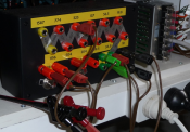
My test box consists of a voltage supply (24 or 36V selectable). I wired a selected series of 1 W resistors between banana sockets and then use clip leads to connect the required channel of a string to the resistors on 1 side and the +ve supply voltage. I have measured the total resistance from each terminal to the string connection point (yellow label in pic). I then use a banana jumper lead to connect the supply volts to the required resistance point. I then use 2 multimeters to measure the voltage across the string and the voltage across the resistors. Total current / channel is then a simple calc from the voltage across the known resistors - I = V/R. The individual LED currents are then obtained from this current by dividing by the number of circuits/channel.
By starting at a high resistance and working to lower values, you can quickly evaluate a current/brightness relationship, and thus what voltage to run the string at, or what resistance to add to run at a different voltage.
I have found that for blue, green and white LEDs, a bulb current of 8-12 mA provides adequate brightness, but for red and yellow, a higher current of 12-18 mA is required to achieve a comparable level of brightness. (My opinion)
First step was to identify the number of channels in the controller and identify the common (ie +ve) wire. Number of separate channels in a string is 1 fewer than the number of wires connecting the controller to the string, (ie 2, 3 or 4). Next step is to work out the number of parallel circuits in each channel and the bulbs/circuit. This can usually be done by checking along the string for the locations where there are the same number of wires between bulbs as there are form the controller to the first bulb. Count the bulbs/ segment and divide by the number of channels.
My test box consists of a voltage supply (24 or 36V selectable). I wired a selected series of 1 W resistors between banana sockets and then use clip leads to connect the required channel of a string to the resistors on 1 side and the +ve supply voltage. I have measured the total resistance from each terminal to the string connection point (yellow label in pic). I then use a banana jumper lead to connect the supply volts to the required resistance point. I then use 2 multimeters to measure the voltage across the string and the voltage across the resistors. Total current / channel is then a simple calc from the voltage across the known resistors - I = V/R. The individual LED currents are then obtained from this current by dividing by the number of circuits/channel.
By starting at a high resistance and working to lower values, you can quickly evaluate a current/brightness relationship, and thus what voltage to run the string at, or what resistance to add to run at a different voltage.
I have found that for blue, green and white LEDs, a bulb current of 8-12 mA provides adequate brightness, but for red and yellow, a higher current of 12-18 mA is required to achieve a comparable level of brightness. (My opinion)
") )
)