Power requirements for WS2815 led strips

Plan-B

New elf
Joined
Oct 20, 2011
Messages
12
Hi all,

I would like to install led pixel strips in my kids room. I have 3, 5 meter strips of 12V WS2815 with 60 pixels per meter. This totals 900 12V pixels. I have a 30 Amp power supply and I'm wondering if that would be sufficient? I am using wLed, so would it be possible to use the current limiting setting if not? I'm also wondering If I can get away with injecting power at both ends of the 15 meter strip run, or if I would need to inject power in the middle as well? Thanks for any light you can shed.
 

Notenoughlights

400,000+ twinkly lights
Joined
Oct 16, 2016
Messages
658
Location
Christchurch, New Zealand
rough calculations show at 100% 900 12v pixels at 100% will pull around 54A. This is just the most basic calculation, with the 60mA rating given by Ali sellers used to calculate. Yes you can still use the 30A power supply, assuming it is one of the legitimate Meanwell power supplies you should be ok up to around 25A (Never best to go full 100% load on a power supply) if it is one of the no-brand supplies, you may run into issues getting the full rating as a lot of those supplies can be "over rated" by the sellers, I've had that experience in the past.

Injecting power may be required in the middle and the end if you were planning on running the entire strip in one length, so power at the first pixel, pixel 450 and pixel 900. Only injecting into the middle, or the end on their own would result in lights turning redder and redder the further they got from the injection point. If you had plans to run them in the 3 5 meter strips, you may find feeding each end with power would be sufficient as that is only 300 pixels, you may notice a little darkening in the middle, unless you use the WLED current limiting setting I mention below.

Limiting power with WLED would be a good choice as you won't have the required output to drive all LED's at 100% white, WLED doesn't physically limit the current, but "calculates" how much current is being drawn and dims the lights down to a level that should stay below the threshold you have set, this is handy to limit the redder and redder issue I mentioned above. This is all done very fast and while it is noticeable, i.e 100% red will be a lot brighter than 100% white, it saves you having to add more power supplies and such should be more than appropriate for some bedroom ambient lighting.
 

TerryK

Retired Elf
Joined
Feb 9, 2020
Messages
655
Location
West Central Ohio
World Semi's WS2815 datasheet indicates 15 mA per pixel so each 5 meter strip (300 pixels) should require about 4.5 Amp at 100% white. For the 3 strips, 13.5 Amp, so your power supply is quite adequate. I've done some testing with the WS2815 strip; don't have those figures available at the moment. I do not remember voltage drop at the string end but if memory serves powering both ends of the 5 meter strip works without color loss. For the 3 strips in series (15 meter total length) I would suggest at least 3 power injection points. If doing this for myself, I'd do 4: both ends and the strip join points.
 

Plan-B

New elf
Joined
Oct 20, 2011
Messages
12
Thank so much for the responses all. I really appreciate it.

I just want to confirm that it is 15 mA per pixel and not 15 mA per RGB color = 45 mA per pixel? At 45 mA per pixel the whole 3 strip run would be at 40.5 Amps, well over the 30 Amp rating of my no-brand, Aliexpress power supply.

Another question has come up. I've set up a single strip to configure and test out wLed and the NodeMcu I've installed it on. It seem to be working as intended for the most part apart from some "glitching" with the lights. Intermittently, the string seems to glitch, causing the lights to flash to full brightness and change colors briefly. I have found the higher I set the current limit parameter in wLed, the more often it does it. If I set the current limit to the default 850 mA, the strip rarely glitches. If I set it to a couple Amps or turn if off all together, it glitches constantly. Any ideas as to why this is and how to correct?

Again, I want to thank you guys for your help in this matter.
 

TerryK

Retired Elf
Joined
Feb 9, 2020
Messages
655
Location
West Central Ohio
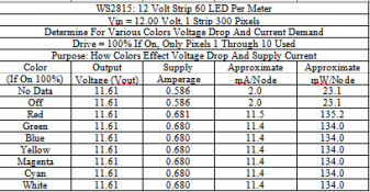
Here is my test data for one of the WS2815 strips I have. The strip is/was obtained from BTF Lighting. Please note that there are WS2815 and WS2815B versions. The RGB for the 'B' version is 10 mA, the other is 15 mA. I no longer remember, do not know if the WS2815s I have are the 'B' version or not.

WS2815 Colors.png

Another note: this data is 'aged' a couple years at this point and I have revised (improved?) how I test pixels. Point being, while the data values are I am certain reasonably accurate, if I were to retest one would find the values shifted by a small percentage.
 

thewanderingpine

Full time elf
Joined
Mar 13, 2021
Messages
318
How did you connect the output on your controller to DI and BI? Somone recently suggested connecting the first BI to ground instead of doing what I naively thought and connecting it to the same data line from the controller.
 

Skymaster

Crazy elf
Global moderator
Generous elf
Joined
Dec 19, 2021
Messages
1,066
Location
Western Sydney
How did you connect the output on your controller to DI and BI? Somone recently suggested connecting the first BI to ground instead of doing what I naively thought and connecting it to the same data line from the controller.
I wouldnt connect them both to the same data source, otherwise, if your main data line was to fail, your first pixel would default to the backup data line, and then the entire chain would be "out by one" as the first pixel will respond to the second pixel worth of data on the line, and so forth.
 

Plan-B

New elf
Joined
Oct 20, 2011
Messages
12
check in wled if you have it set to the right type led strip and colour order
Checked and double checked Fugley. This was my first thought as well, but I think I have all settings in order. Thanks for the comment.

Here is my test data for one of the WS2815 strips I have.
Thanks Terry. That helps put my mind at ease. Before reading your post, I put my cheap multimeter in series with the strip and got a reading of 4.1 Amps. Very close to what you said to expect. I feel fairly confident now that I won't burn my kids room down. I was so worried about the current draw, I dropped the ball and forgot to test the voltage drop. I'll have to test that as well tonight.

How did you connect the output on your controller to DI and BI? Somone recently suggested connecting the first BI to ground instead of doing what I naively thought and connecting it to the same data line from the controller.
I actually don't have BI hooked up at all. As I understood it, BI is a backup data channel and not really needed for operation. I will try connecting it to ground and see if there is any improvement. Currently, I'm using a cheap, 6" breadboard jumper to connect D4 of the controller directly to DI on the strip. I'm pretty sure those are only 28 AWG. With the short, 6" run, I thought it would be sufficient and I wouldn't require a level shifter or sacrificial pixel. Maybe that's my issue and the 3.3v off the board is not cutting it for the 5v data line? I've also read a few places that putting a low ohm resister in series with the data line can help smooth out signal. Unfortunately, I have nether resistor or level shifter to test the theory out.
 

Plan-B

New elf
Joined
Oct 20, 2011
Messages
12
Quick follow up. I just tried what Pine suggested and connected BI to ground. This made a huge improvement, but didn't rectify the problem entirely. I am now able to turn the current limit up to 2 Amps before I start to see the glitching and flashing issues. If I turn the current limit off and go full brightness, I completely lose control of the strip. I'm still able to access the controller, but the data doesn't seem to make it to the strip and it remains at full brightness until I disconnect the power supply from mains.

It looks to me like this is definitely a data signal strength issue. I seems like as the current in the strip rises, it interferes more and more with the data channel. I'm assuming connecting BI to ground somehow helps shield it by diverting noise away? It probably also doesn't help that I have the strip coiled on my desk with the data line running to the center to connect to the input.

My noob intuition is telling me that using solid, higher AWG data wiring with soldered connections, a level shifter to boost the data signal from 3.3v to 5v, a resistor to smooth out the data signal and moving the data line away from the coiled strip would probable rectify all my issues and allow me to run the strip at 100% power. But, I'm just not positive all, or any of that is really required and maybe I'm missing something in my ignorance and inexperience. I'm very curious to know what the experienced people of this forum think about the situation.

Again, I just want to thank everyone for their time, help and input in this matter. I don't think I could have gotten as far in this project as I have without the support I'm receiving. Cheers!
 

TerryK

Retired Elf
Joined
Feb 9, 2020
Messages
655
Location
West Central Ohio
How did you connect the output on your controller to DI and BI? Somone recently suggested connecting the first BI to ground instead of doing what I naively thought and connecting it to the same data line from the controller.
I do not remember how I had the backup input connected when I tested the WS2815s. I would assume I followed the IC's datasheet which shows the backup input for pixel #1 connected to GND.
 

TerryK

Retired Elf
Joined
Feb 9, 2020
Messages
655
Location
West Central Ohio
@Plan-B From your description, it does sound as if the data input is losing the reference to GND as string illumination levels increase. This happens due to voltage rise in the GND line. The Voltage Rise term can be a bit confusing but the voltage drop in GND causes the voltage along GND to rise as referenced to the original 0 voltage point. In your situation, probably from the controller connections. Indirectly this causes the data line to no longer be correctly referenced to GND. Pixels locking at full on or full white has been discussed in other Forum Threads and is also related to the data line input losing its 0 reference.

Some pixels will accept a 3.3 volt data signal well, others not so much. All due to several factors, voltage drop being one of the primary causes. Data line impedance matching (the resistors you mentioned) plays a role too but you had mentioned 6 inch leads. I'm somewhat inclined to dismiss the resistors with connections that short. The 28 AWG though is definitely small.
 

Plan-B

New elf
Joined
Oct 20, 2011
Messages
12
Thanks Terry,

I rewired the controller using 22 AWG wire and the problem has been corrected.
 
This thread is very old. An answer might not be needed anymore.
Top