Powering two LRS-350-5's from the same power cord and best practice

janastas

Full time elf
Joined
Nov 30, 2020
Messages
120
Hi all,

Been some time since I've been on the forums but I have been keeping busy in the background.

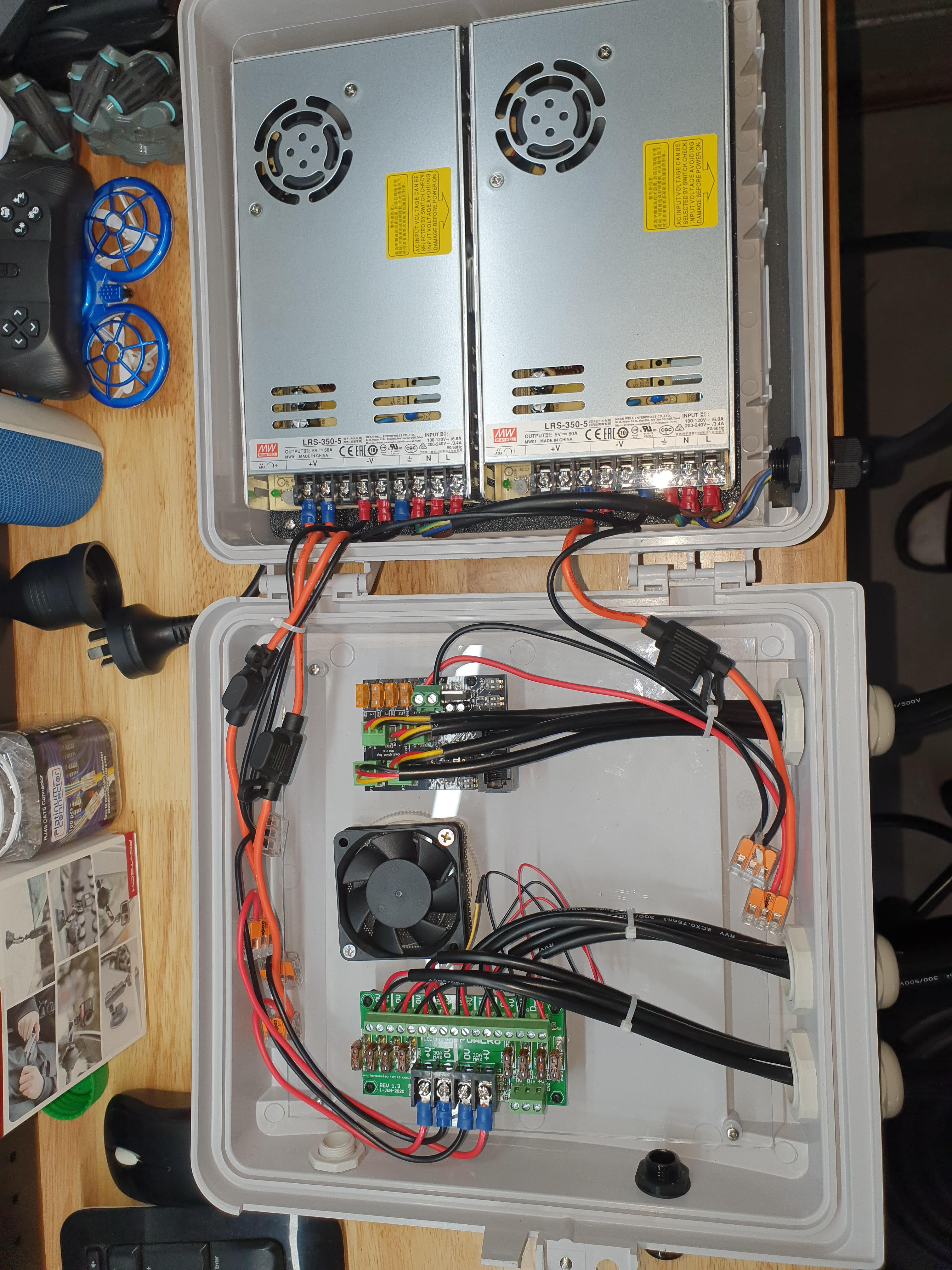
I've built myself a CG-1500 box that contains the following:
  • x2 Meanwell LRS-350-5 power supplies
  • x1 HE Power8 distro board
  • x1 Falcon smart receiver
The aim is to utilise the two power supplies to power as many pixels as I can off the single smart receiver (The plan is to run brightness at around 30% so should easily be able to power around 2,500 pixels)

Two questions I had regarding AC and DC power:

  1. The AC power coming into the two power supplies - I've connected L / N / GND wires to power supply 1 accordingly then L from PS1 to L on PS2, N from PS1 to N on PS2 and the same for GND. Is this the correct way to power two 5v power supplies from the same power cord?
  2. DC negatives - do i need to connect to the DC -ve's between the two power supplies?
Picture of my box setupbelow if it helps answer the questions above. The setup is very similar to what Ni family lights does on youtube if you want to have a look at their build.


AAH

I love blinky lights :)
Community project designer
Joined
Dec 27, 2010
Messages
4,188
Location
Eaglehawk
The mains wiring is fine. I would always provide a secondary strain relief on the mains. In addition to the cable gland I would typically either cable tie the power cable to the power supply or cable tie a knot in the lead so that the cable can't get pulled out if the gland is loose.
A couple of notes or concerns. The fuses inline between the power supplies and the power8 and diff boards aren't really needed. All fuses have a voltage drop across them and for 5V it's important to minimise the losses. I would just wire direct between the power supplies and the boards with cables of 3mm2 or bigger.
I'm not sure what the current rating is for the WAGO connectors but you don't really need them there. With the hardware there I'd swap the fuses in the inline fuseholders down to 7.5A and use them and the WAGO connectors in order to give a couple extra power injection pigtails.
 

janastas

Full time elf
Joined
Nov 30, 2020
Messages
120
The mains wiring is fine. I would always provide a secondary strain relief on the mains. In addition to the cable gland I would typically either cable tie the power cable to the power supply or cable tie a knot in the lead so that the cable can't get pulled out if the gland is loose.
A couple of notes or concerns. The fuses inline between the power supplies and the power8 and diff boards aren't really needed. All fuses have a voltage drop across them and for 5V it's important to minimise the losses. I would just wire direct between the power supplies and the boards with cables of 3mm2 or bigger.
I'm not sure what the current rating is for the WAGO connectors but you don't really need them there. With the hardware there I'd swap the fuses in the inline fuseholders down to 7.5A and use them and the WAGO connectors in order to give a couple extra power injection pigtails.

Thanks for the feedback @AAH - Will remove the in line fuses from the power supplies to the distro board and smart receiver and repurpose for power injection.

I believe each WAGO connector can handle up to a 12AWG wire size so guessing max of around 30A?
 

Mark_M

Annoying Elf
Joined
Dec 30, 2018
Messages
914
Location
Christmas Light world
The aim is to utilise the two power supplies to power as many pixels as I can off the single smart receiver (The plan is to run brightness at around 30% so should easily be able to power around 2,500 pixels)
Are you sure you want to do this?

The test mode of the smart receiver is set to 100% and assumes there's 1000 pixels on each port. That would send all 2,500 you want to 100% brightness.
Similar for the main controller, it's set for 100% brightness by default.

If you are going down this route; check the controller after every settings push from xLights and have plenty of fuses spare.
At last minute when you least expect, you'll accidently do it.
 

janastas

Full time elf
Joined
Nov 30, 2020
Messages
120
Are you sure you want to do this?

The test mode of the smart receiver is set to 100% and assumes there's 1000 pixels on each port. That would send all 2,500 you want to 100% brightness.
Similar for the main controller, it's set for 100% brightness by default.

If you are going down this route; check the controller after every settings push from xLights and have plenty of fuses spare.
At last minute when you least expect, you'll accidently do it.

Thanks @Mark_M When I was building the box I was just testing 50 pixels attached to each port.

When I setup everything in the yard I'll make sure all the outputs from FPP are set to 30% before I kick off any light tests which I'll be running directly from FPP
 

Mark_M

Annoying Elf
Joined
Dec 30, 2018
Messages
914
Location
Christmas Light world
When I setup everything in the yard I'll make sure all the outputs from FPP are set to 30% before I kick off any light tests which I'll be running directly from FPP
I suggest setting brightness from the controller. That way you can still push the test button on the controller (F16/F48) and it won't send to 100%.
Pushing a button on the controller is a lot easier than bringing your phone out and logging in to test.

Doing it on FPP also means that xLights may bypass it while outputting to lights.
Ways around is setting FPP to have the controller on a separate network and force routing though the Pi. That does mean you'll have to tell xLights the controller is routed through the Pi when applying configuration changes.
 

i13

Dedicated elf
Joined
Jul 5, 2013
Messages
1,172
There might not be a perfect answer for whether to connect the negative outputs from to power supplies to each other. They already be connected together if they're connected to the same controller somewhere. The reason for connecting them is that the negative is used as a reference for the data. If pixels running end-to-end are all on the same supply then it'll make no difference whether the negatives are connected between the supplies. If there are pixels on different power supplies running end-to-end then you could connect the negatives together at the power supplies instead of through the strings of pixels. The advantage in doing it this way is that it avoids creating negative loops when you have multiple strings of pixels going from one power supply to the other. Negative loops can (but rarely do) cause flicker. The disadvantage is that you're cutting the negative within the string of pixels so the reference at that point is not as stable due to voltage drop. The alternative (which is what I do) is to connect the negatives together through the strings of pixels instead of at the power supplies. In reality, both options should work. If you get flicker with one option, try the other.
 

janastas

Full time elf
Joined
Nov 30, 2020
Messages
120
Thanks All,

Brightness is being set from the controller and and I'm confirming in the FPP settings output screen that all ports and models are at 30% so all good from that end.

The only other thing I wanted to check is breaking the V+ in the strings to get the maximum number of pixels per port using power injection.

Each smart receiver port has a 5A fuse so at 30% brightness II'll be able to get 300 pixels (5A / (0.055A per pixel x 30%)
Question: For 5V pixels you would get around 100 pixels in before you would need to power inject - what's the easiest way to continue utilizing power off the smart receiver port for an additional 200 pixels after the first 100 or do I just resort to breaking V+ at this point and power inject from my distro board?

Then assuming I'de have to break v+ at the end of the first (100 / 300 pixels) (I have a power injection tee that breaks v+) then use the power distro board for power injection at that point?

Each connector on the power distro board has a 7.5A fuse so assuming I could get an additional 450 pixels (7.5A / (0.055A per pixel x 30%)

So depending on the response to my question above I can get:

  • Around 750 pixels off a single port (300 pixels direct from the port + 450 pixels using power injection from a single port on the distro board)
  • Around 550 pixels off a single port (100 pixels direct from the port + 450 pixels using power injection from a single port on the distro board)
Any thoughts on the above?
 

TerryK

Retired Elf
Joined
Feb 9, 2020
Messages
655
Location
West Central Ohio
The approximate 100 pixels before power injection is based on 100% White (and generally 18 AWG WS2811 pixels). If your drive level is 30% then the number of pixels before power injection is necessary increases.

Providing the drive never exceeds 30%, your 5 Amp calculation would indicate the 300 pixels will drive fairly well from a single receiver port. AWG size and cable distances need factored in of course. There are numerous methods of power injection; what's best is usually a personal opinion. If a spare receiver port is available, a 5 Amp connection could be used/obtained there. Breaking the V+ has advantages/disadvantages; depends on your expectations and display design.
 

janastas

Full time elf
Joined
Nov 30, 2020
Messages
120
The approximate 100 pixels before power injection is based on 100% White (and generally 18 AWG WS2811 pixels). If your drive level is 30% then the number of pixels before power injection is necessary increases.

Providing the drive never exceeds 30%, your 5 Amp calculation would indicate the 300 pixels will drive fairly well from a single receiver port. AWG size and cable distances need factored in of course. There are numerous methods of power injection; what's best is usually a personal opinion. If a spare receiver port is available, a 5 Amp connection could be used/obtained there. Breaking the V+ has advantages/disadvantages; depends on your expectations and display design.

So I was using spiker lights (http://spikerlights.com/calcpower.aspx) to confirm my calcs above, I just want to make sure I was doing it right for 300 pixels.

See the screenshot below, my question is around the watts per pixel.

If you select 5V it defaults to 0.3W, I'm assuming this is at 100% brightness, I'm guessing I also need to adjust this to be 0.3W x 30% = 0.09W?

If that's the case then is the below correct or do I need to keep watts per pixel and 0.3W?


TerryK

Retired Elf
Joined
Feb 9, 2020
Messages
655
Location
West Central Ohio
Hmm, that's interesting. Well first, I have not used this calculator and its results appear accurate. Took me a bit of toying but I can see where your puzzlement is originating from. The inter-action of the pixel wattage and drive intensity seems a bit odd to me as well. I wouldn't mind seeing 'behind the curtain' formulas. For your scenario I would suggest using 0.3 Watt Per Pixel and 30% Drive Intensity. Using 0.09 Watt Per Pixel and 100% Drive Intensity gives about the same result. Five volt and 0.55 Amp pixel is 0.275. Rounding that up to 0.3 changes the numbers a bit but not enough to be terribly significant.

I would also like to clarify what I had indicated previously. If one knows that the 300 pixels will not exceed 5 Amps then they can all be driven from a single 5 Amp port. The problem is the voltage drop seen across/downstream on the string. That is what the Spiker Chart is showing; voltage drop in the 160/170 pixel range becomes a problem. A solution, a bit unusual, would be to power inject pixels 160/170 to the end also from the same port.
 
Last edited:

janastas

Full time elf
Joined
Nov 30, 2020
Messages
120
So I ran a test last night on the 550 pixel scenario at 30% with two power injections
  • 100 pixels from the smart receiver port
  • add a power injection tee to the end of the 100 pixels above which has v+ cut from the last pixel
  • connect another 300 pixels to the end of the tee above
  • add another power injection tee after pixel 300 and power inject again
  • connect another 150 pixels to the other side of the tee
Based on the above I was expecting the following voltage drop based on spiker lights


Setup looked as follows in my garage


Ran some solid color tests to see if there's was any flicker or loss of color and nothing that I could pick out even with all the lights off.

Also ran it through some sequences I have started setting up for halloween and all looked ok.

One thing to note, I'm just using one port from the power8 distro board for the two power inejctions.

So it looks like I can get 550 pixels with the controller port and a single port on the distro 8 (but getting two power injections off the single distro 8 port)

I'm happy with that. just using the 4 smart receiver ports and the power injection above I can then get 2,200 pixels.
 

TerryK

Retired Elf
Joined
Feb 9, 2020
Messages
655
Location
West Central Ohio
Remember, the chart and formulas are based with White, usually 100% White. The solid color tests will depending upon color be a percentage of the 30%.

Toying with the Spiker Chart a little more, it does not seem to be able to properly calculate a broken V+ at power injection points. You have 450 pixels in the chart but mention 550 pixels so I tweaked that and also added the 3rd power injection. Got this:
1625169337773.png
Not much different from yours. Notice the dip at or near pixel 50 which indicates that the V+ is not broken at the Pixel 100 Power Injection. Something similar should be seen at the injection point near Pixel 400.

Based on how I interpreted what you posted I expected something like this:
1625169550225.png
Required a little cut and paste to create; essentially 3 sections (100, 300, and 450 pixels) powered at pixels #1, #100/#101, and #400/#401 with the V+ broken at the injection points. This seems to agree from what I can determine from the hardware on the table.

At this point I'm curious why your tests worked all right. Did I misinterpret what you posted? Are the TEEs breaking V+ as you expect?
 

janastas

Full time elf
Joined
Nov 30, 2020
Messages
120
Sorry I forgot to mention i didn't bother putting the first 100 pixels in the spiker lights calc, the calc graph is only for the next 450 pixels.

The pixels lengths were as follows:

controller port 1 -> 100 pixels -> v+ break -> power injection -> 300 pixels -> power tee (no v+ break) -> 150 pixels.

I'll set it all up again tongiht and take some videos to show what the colors look like.
 
Top