
Hi All,
Have been meaning to post this for a little while. Below is information that i presented at the Perth Mini 10 June 2023.

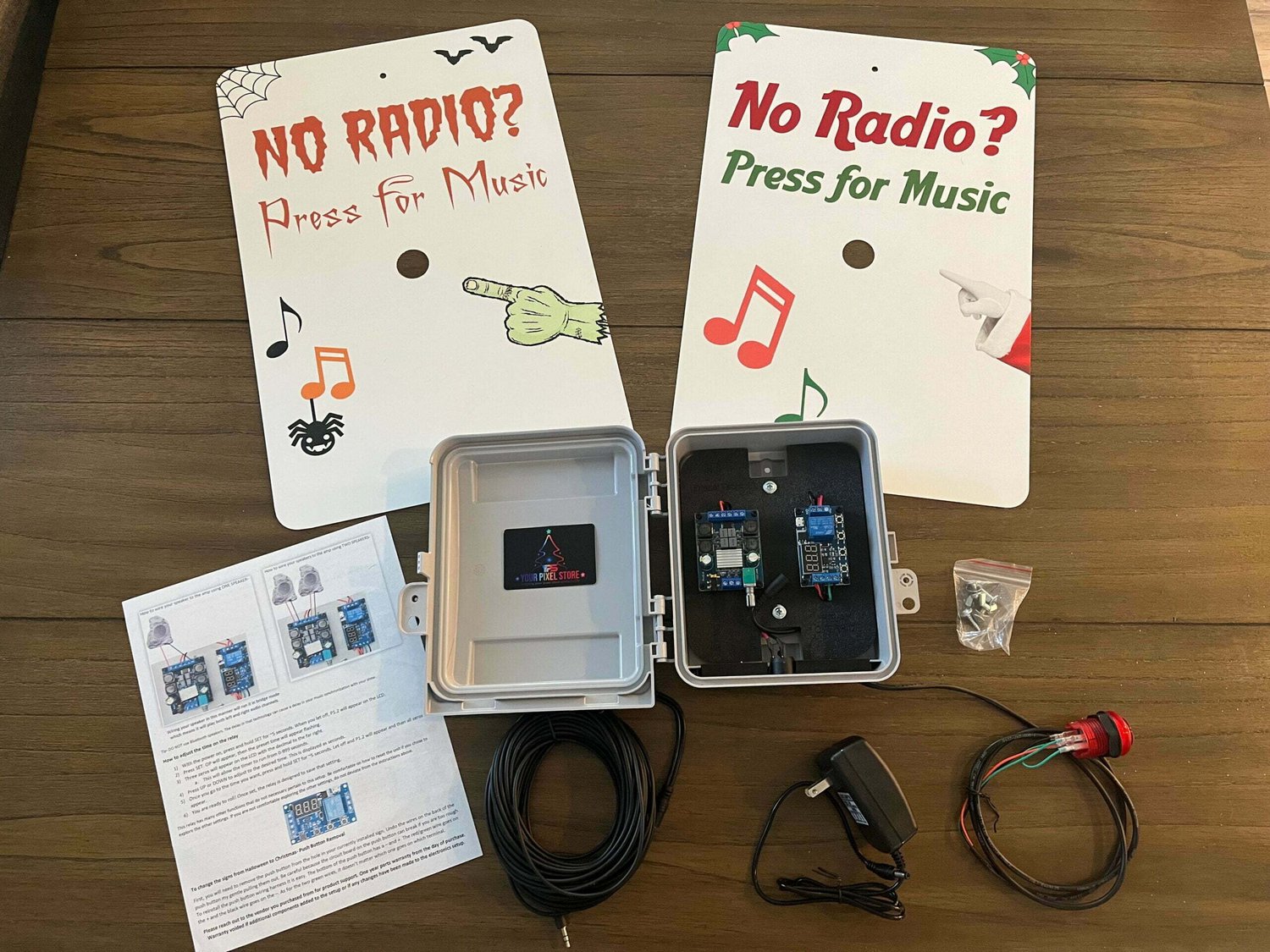
Note: only one speaker wire is connected (red/black wires) as I was testing when i took the photo.
Purpose
Purpose of the push button speaker box is to enable speakers in your display to only play for a set amount of time based on a button push, and then switch off so the neighbors aren't hearing music all the time.
Inspiration
(7) VCS 2020 Push Button Speaker - Keith Peffer - YouTube
The Keith Peffer design is great, but even since 2020, the majority of links included in the video description are broken and I could not fine the most of the items online. My design uses the most common components available at multiple venders on AliExpress/Amazon/eBay as of June 2023. This will likely change but will be a good starting point. I've also included full item descriptions if the links stop working due to vendor changes etc.
Commercial Options
Similar commercial options are available from yourpixelstore for $225USD plus shipping. These boxes look great but do not have a FM receiver in them and rely on long 3.5mm audio cable from the push button box to your soundcard/PC/controller.
 yourpixelstore.com
My Design
The Main difference to the commercial option above is the inclusion of the FM receiver. This avoids having to run an audio cable and only a single Power Injection 12v/5v point to function as well as the 2 speaker outlets. you could power from any 5/12v source but as we all seem to have Power Injection/Power Balancing wires running everywhere, its an easy option.
What you need to put it all together
Shopping List
Photos of all the items

Other Misc Items
Speaker Wire
3 core cable
Connector to external Power - I used Xconnect 2pin
Heat shrink
Crimp Connectors
Plastic screws/spacers/nuts
Speakers (outdoor rock speakers work great and blend in)
5/12v power source
FM Transmitter
Audio Source - output from Pi/BBB/External Soundcard/PC etc
Tools
Hot Glue Gun
Soldering Iron
Drill
Small hand tools
Stepped drill bit/Forster bit
Wiring Diagram

Push Button Wiring

Switch/button/trigger wiring – Brown & Blue
LED wiring – Brown & Green/yellow
Note: Brown & Blue could be wired in either location. Pushing the button completes the circuit and provides voltage to the trigger input and activates the relay.
Box Construction
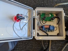
There are no mounting hardware on the top of this box, so I hot glued some M4 plastic bolts to the top and then added some spacers and used plastic nuts to fix in place. I also used this method of hot glue on the bottom of the box as well. If i used a larger box i would have mounted the items on a bottom plastic/acrylic plate.

Wiring up the FM Receiver
The FM Receiver doesn't come with power connections and you need to solder directly onto the board. I am not the greatest at soldering and managed to get it attached reasonably easily. You will also need to source and attach an antenna wire. This can be any single strand wire you have lying around, i had some light blue wire from a previous project, needs to be reasonably thin. About 60cm/2foot in length should be enough. At the moment i have the antenna wire coiled up in the box, but I may need to feed it though a cable gland if the signal is not strong enough. Tell me how yours works!

Programming
Operating modes:
Have been meaning to post this for a little while. Below is information that i presented at the Perth Mini 10 June 2023.
Note: only one speaker wire is connected (red/black wires) as I was testing when i took the photo.
Purpose
Purpose of the push button speaker box is to enable speakers in your display to only play for a set amount of time based on a button push, and then switch off so the neighbors aren't hearing music all the time.
Inspiration
(7) VCS 2020 Push Button Speaker - Keith Peffer - YouTube
The Keith Peffer design is great, but even since 2020, the majority of links included in the video description are broken and I could not fine the most of the items online. My design uses the most common components available at multiple venders on AliExpress/Amazon/eBay as of June 2023. This will likely change but will be a good starting point. I've also included full item descriptions if the links stop working due to vendor changes etc.
Commercial Options
Similar commercial options are available from yourpixelstore for $225USD plus shipping. These boxes look great but do not have a FM receiver in them and rely on long 3.5mm audio cable from the push button box to your soundcard/PC/controller.
Steve’s Push Button Setup - Your Pixel Store
Steve’s Push Button Setup – The push button setup is a great addition to a pixel light show that is synchronized to music. Steve’s Push...
My Design
The Main difference to the commercial option above is the inclusion of the FM receiver. This avoids having to run an audio cable and only a single Power Injection 12v/5v point to function as well as the 2 speaker outlets. you could power from any 5/12v source but as we all seem to have Power Injection/Power Balancing wires running everywhere, its an easy option.
What you need to put it all together
Shopping List
| Store | Item | Number | Cost | Total |
| Digi Key | Bud Box - NBF32004 - 149.86 x 99.82x x 69.85 | 1 | $ 16.91 | $ 16.91 |
| https://www.digikey.com.au/en/products/detail/bud-industries/NBF-32004/2328534 | ||||
| AliExpress | 33mm Arcade Push Button Led Momentary illiminated Transparent Buttons with Micro Switch Cabinet Accessories | 1 | $ 6.41 | $ 6.41 |
| Arcade Game 100mm Push Button | Sport Push Buttons Arcade | Push Button Arcade Spare - Coin Operated Games - Aliexpress | ||||
| AliExpress | 9V 12V 24V to 5V DC-DC Step Down Charger Power Module Dual USB Output Buck Voltage Board 3A Car Charge Charging Regulator 6-26V | 1 | $ 2.64 | $ 2.64 |
| 9V 12V 24V to 5V DC DC Step Down Charger Power Module Dual USB Output Buck Voltage Board 3A Car Charge Charging Regulator 6 26V| | - AliExpress | ||||
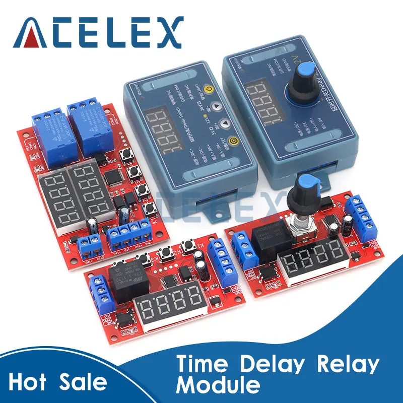
| AliExpress | DC 6-30V Support Micro USB 5V LED Display Automation Cycle Delay Timer Control Off Switch Delay Time Relay 6V 9V 12V 24V | 1 | $ 3.82 | $ 3.82 |
| DC 6 30V Support Micro USB 5V LED Display Automation Cycle Delay Timer Control Off Switch Delay Time Relay 6V 9V 12V 24V|Integrated Circuits| - AliExpress | ||||
| AliExpress | GREATZT DC 12V 24V 120W*2 TPA3116 D2 Dual Channel digital Power audio amplifier board | 1 | $ 9.99 | $ 9.99 |
| GREATZT DC 12V 24V 120W*2 TPA3116 D2 Dual Channel digital Power audio amplifier board good|Integrated Circuits| - AliExpress | ||||
| AliExpress | GREATZT PG7 Black Waterproof Plastic Nylon Cable Gland Connectors Joints | 4 | $ 0.88 | $ 3.52 |
| GREATZT 10pcs PG7 Black Waterproof Plastic Nylon Cable Gland Connectors Joints| | - AliExpress | ||||
| AliExpress | FM Radio Receiver Module Frequency Modulation Stereo Receiving PCB Circuit Board With Silencing LCD Display 3-5V LCD Module | 1 | $ 16.95 | $ 16.95 |
| https://www.aliexpress.com/item/400....order_list.order_list_main.44.621b1802FSnWz6 | ||||
| AliExpress | 3.5mm AUX to 3 pin | 1 | $ 5.11 | $ 5.11 |
| 1pc 30cm Jack 3.5mm AUX Audio Cable To XH2.54 3p Terminal Male To Male Female 3 Core Stereo Audio Cable Amplifier Extended Line|Connectors| - AliExpress | ||||
| *Prices as of 20/05/2023 (all prices inc shipping in AUD) | $65.35 |
Other Misc Items
Speaker Wire
3 core cable
Connector to external Power - I used Xconnect 2pin
Heat shrink
Crimp Connectors
Plastic screws/spacers/nuts
Speakers (outdoor rock speakers work great and blend in)
5/12v power source
FM Transmitter
Audio Source - output from Pi/BBB/External Soundcard/PC etc
Tools
Hot Glue Gun
Soldering Iron
Drill
Small hand tools
Stepped drill bit/Forster bit
Wiring Diagram
Push Button Wiring
Switch/button/trigger wiring – Brown & Blue
LED wiring – Brown & Green/yellow
Note: Brown & Blue could be wired in either location. Pushing the button completes the circuit and provides voltage to the trigger input and activates the relay.
Box Construction
There are no mounting hardware on the top of this box, so I hot glued some M4 plastic bolts to the top and then added some spacers and used plastic nuts to fix in place. I also used this method of hot glue on the bottom of the box as well. If i used a larger box i would have mounted the items on a bottom plastic/acrylic plate.
Wiring up the FM Receiver
The FM Receiver doesn't come with power connections and you need to solder directly onto the board. I am not the greatest at soldering and managed to get it attached reasonably easily. You will also need to source and attach an antenna wire. This can be any single strand wire you have lying around, i had some light blue wire from a previous project, needs to be reasonably thin. About 60cm/2foot in length should be enough. At the moment i have the antenna wire coiled up in the box, but I may need to feed it though a cable gland if the signal is not strong enough. Tell me how yours works!
Programming
Operating modes:
- P1.1:signal is triggered again, invalid - Multiple pushes the button and it does nothing, ie timer from first push is length of activation
- P1.2:signal is triggered again, the clock is reset - Each button push resets the timer from the beginning
- P1.3 - P4 - Not used
- 0.1 seconds (min) to 999 minutes (max) continuously adjustable
- How to choose the time range?
- After setting the mode selection screen parameter value by a short press "STOP" button to select the time range;
- XXX. decimal point in the unit place, time range: 1 second to 999 seconds.
- 1. X decimal point indecade place, Timing range: 0.1 seconds to 99.9 seconds
- 2. X. X. decimal full brightness, Timing range: 1 minute to 999 minutes.
- For example, you want to set Operational time to 3.2 seconds, then move the decimal point to decade place, the digital display 03.2
- The module is powered up, the display at the current work mode (P1.1 default mode), then enter the main interface; press "SET" button for 2 seconds after release to enter mode selection interface; a short time by pressing "UP", "DOWN" key to select the mode (P1.1 ~ P-4).
- Select the mode (such as P3.2), short press the "SET" button, then the parameter to be set flashes ( "OP" on-time, "CL" off time, "LOP" cycles ( "---" represents infinite loop)), by "UP", "DOWN" keys to adjust the parameter value, support long press (rapid increase or decrease) and short press (increase or decrease one unit); then short press the "STOP" key to select the decimal point position, select the time range (0.1 seconds to 999 minutes); short press the "sET" button to set the next parameters of the current mode of procedure is as above.
- After the parameters are set, long press "SET" button for 2 seconds then release, the name of the current mode will flash once, and then return to the main screen, set the parameters of success!
- The main interface: In the relay does not work status display "000" (no decimal point), with a decimal point under relay state.
- Mode selection screen:Long press the "SET" key to enter, after setting is completed, long press the "SET" key to exit back to the main screen.
Last edited:


")