Rather than use a NUD4001 which has a fairly limited power dissipation and needs to be on a pcb in order to get rid of heat effectively it's quite easy to use an LM317 which can be heatsinked easily. The voltage variation is easily taken care of with this method.Thanks for that great info AAH.
I did find this link to the NUD4001 data sheet. On it there is an example using two of the NUD4001 for a dome light application. But that dome light application is using a single LED and thus, a high watt resistor, which I don't really want to do - it doesn't apply to my LEDs.
So could I just use figure 6 for the dome light situation, putting 3 LEDs in series and a lower wattage resistor like you mention above? For each of the small boards I received from the group buy from years ago, I could make one of these (with 3 LEDS wired in per board) for each of his shelves and run 12v to each one to give lighting useful for him to find his tools in the dark.
Navigation
Install the app
How to install the app on iOS
Follow along with the video below to see how to install our site as a web app on your home screen.
Note: This feature may not be available in some browsers.
More options
You are using an out of date browser. It may not display this or other websites correctly.
You should upgrade or use an alternative browser.
You should upgrade or use an alternative browser.
Putting strobes together
- Thread starter toodle_pipsky
- Start date
I searched Mouser for LM317 in the same SO-8 package that the NUD4001 is in so I can use it on the same board that came in the group buy. The only LM317 I found has just a 100ma current rating, while the NUD4001 is 500ma.
Unless my search capabilities suck....which they might.
If I make the strobe kits like the instructions state on post 1 of this thread, but leave off the PIC, can I run 3 of the LEDs off of it at 12v DC (or whatever level the van is at during running, not running, etc)? I think using 18Ohm, 1/2w for R2. Or, what parts may not be needed?
I'm wondering if I don't use the PIC, if the board will even work as a voltage/current regulator function....
I wouldn't use the board at all. A TO-220 LM317 is rated at 1.5A and is pretty easy to provide heatsinking of. Screwing it to almost any metal surface will probably be enough to dissipate the 1/2W roughly of heat. The NUD on the strobe board can get away with such a small pcb as the led is on probably signicantly less than 10% of the time. For using as illumination it will need to be on 100% so it would overheat well within 1 minute I'd reckon.
Thanks for that info.
In post #1 and #2 of this forum, it mentions using the LM317 as a constant current source for LEDs, not a constant voltage source. People mention that the LED is a current device, not a voltage device, and the voltage is less important (though if you look at Ohm's law, how can that be?).
I might only be able to use 2 LEDs per regulator due to the fact that the regulator has a considerable voltage drop also.
In the hand-drawn schematic I'm not sure how they say 1.25v is going to power their LED (I=1.25v / R1). So, I'm a bit confused there.
Sorry for the bad diagram below. I can't get the correct spacing without all the dots, etc in there. Imagine those 2 vertical lines are moved over...one under the LM317 and the other under the 18 Ohm resistor.
+12v DC <-----> In LM317 Out <--> 18 Ohm
. . . . . . . . . . . . . . . . . . Adj . . . . . . . . . . . . . .|
spacer to get lines. . . . |.moved over . . . .|
GND < -D1-D2-D3-->---|-------------------------|
Would this work with my LEDs? Or, I could drop it down to 2 LEDs if needed. But would the 18Ohm resistor need to change?
I did find this on the datasheet also, which I guess is similar. I'm not sure what the 1.2 is in the diagram. is it voltage? Can I just use a 9 Ohm resistor for R1 and put 2 of the 1/2 watt LEDs (or 1 watt - whatever they are) on the load?
Last edited:
Thanks for that info.
In post #1 and #2 of this forum, it mentions using the LM317 as a constant current source for LEDs, not a constant voltage source. People mention that the LED is a current device, not a voltage device, and the voltage is less important (though if you look at Ohm's law, how can that be?).
I might only be able to use 2 LEDs per regulator due to the fact that the regulator has a considerable voltage drop also.
In the hand-drawn schematic I'm not sure how they say 1.25v is going to power their LED (I=1.25v / R1). So, I'm a bit confused there.
Sorry for the bad diagram below. I can't get the correct spacing without all the dots, etc in there. Imagine those 2 vertical lines are moved over...one under the LM317 and the other under the 18 Ohm resistor.
+12v DC <-----> In LM317 Out <--> 18 Ohm
. . . . . . . . . . . . . . . . . . Adj . . . . . . . . . . . . . .|
spacer to get lines. . . . |.moved over . . . .|
GND < -D1-D2-D3-->---|-------------------------|
Would this work with my LEDs? Or, I could drop it down to 2 LEDs if needed. But would the 18Ohm resistor need to change?
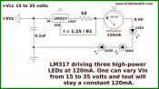
I did find this on the datasheet also, which I guess is similar. I'm not sure what the 1.2 is in the diagram. is it voltage? Can I just use a 9 Ohm resistor for R1 and put 2 of the 1/2 watt LEDs (or 1 watt - whatever they are) on the load?View attachment 13048
Leds are referred to as "current devices" due to the fact that the voltage across them changes a reasonable amount depending on the current flowing through them.
I didn't really think too much about the dropout voltage for the LM317. It's about 3V and the reference voltage which gets dropped across the current set resistor is 1.25V. With the forward voltage of the leds being somewhere in the vicinity of 3V (current dependent) the leds might not reach the full current when the vehicle isn't running as the 12.7V battery voltage is borderline enough. When the alternator is spinning over and the battery is being charged at about 13.8V there will be ample. What this means is that when the vehicle isn't running the leds may not be at full brightness but they will be when it is running. In both cases they will be protected against over current though. Using 2 leds in series would give you consistent brightness at all times but at the expense of dumping more heat into the LM317.
For a current of 300mA a resistor of 4.2 ohms would be needed. A 4.7 ohm 0.5W resistor would do but personally I'd go with either a 3W or 5W to keep it a bit cooler.